Few of us will ever find ourselves piloting a full-sized military tank. Instead, you might like to make do with the RC variety. [TRDB] has whipped up one of their own design which features a small little pellet cannon to boot.
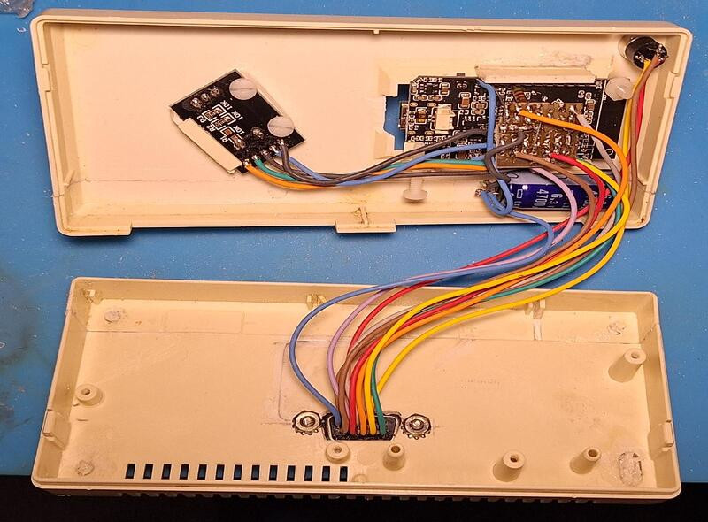
The tank is assembled from 3D printed components — with PETG filament being used for most of the body and moving parts, while the grippy parts of the treads are printed in TPU. The tank’s gearboxes consist of printed herringbone gears, and are driven by a pair of powerful 775 brushed DC motors, which are cooled by small 40 mm PC case fans. A rather unique touch are the custom linear actuators, used to adjust the tank’s ride height and angle relative to the ground. The small cannon on top is a flywheel blaster that fires small plastic pellets loaded from a simple drum magazine. Running the show is an ESP32, which responds to commands from [TRDB]’s own custom RC controller built using the same microcontroller.
As far as DIY RC tanks go, this is a very complete build. We’ve seen some other great work in this space, like this giant human-sized version that’s big enough to ride in.

 Peek behind the polished face and you’ll find a mechanical sleight of hand. This isn’t your grandfather’s gear-laden