Interested in taking some wild new 3D printing features for a test drive? preFlight is a free and open source slicer that brings a host of processing improvements as well as fascinating new features and interesting twists on old ones. There are almost too many to list, so here are a few that caught our eye.
Want to mix and match different support types on the same object? No problem. How about use Nip & Tuck seams to better hide where layers start and stop? You can emboss images directly onto print surfaces with a real-time preview and use smart bridging for counter-bored holes. We particularly like the ability to preview a sliced object from the side instead of just by layer. That’s not all, either.
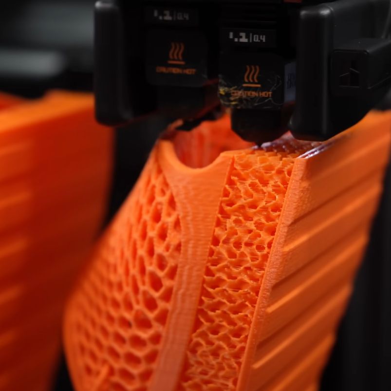
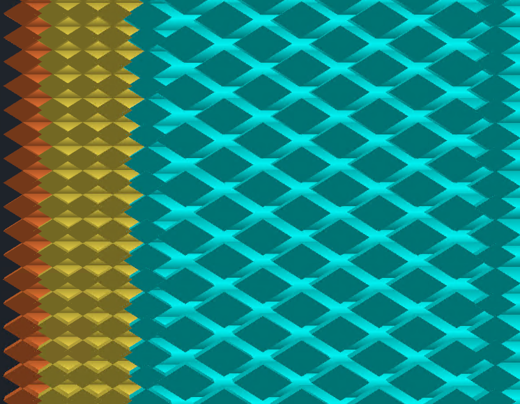
Those features alone are pretty intriguing, but there’s one in particular that is particularly relevant to creating stronger parts. Interlocking Perimeters increases layer bonding to increase object strength. Unlike brick layers, which staggers layers vertically, interlocking perimeters plays with spacing and compression to increase bonding in the Z axis while keeping layer heights constant. This is possible thanks in part to the greater control offered by Athena, the new perimeter generator.
There are plenty more features — like a full Python runtime embedded directly into the slicing pipeline, and a host of export pathways — so check out the GitHub repository for added detail and let us know in the comments if you give it a try.


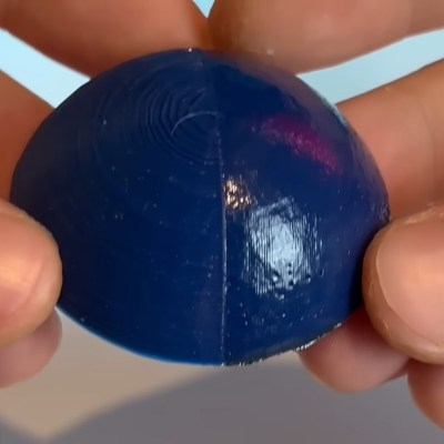 The smoothing process begins at the end of a 3D print and uses non-planar printer movements to keep the laser at an ideal focusing distance. The results proved rather effective, giving a noticeably smoother and shiner quality than an unprocessed print. The smoothing works incredibly well on fine geometry which would be difficult or impossible to smooth out via traditional mechanical means. Some detail was lost with sharp corners getting rounded, but not nearly as much as [TenTech] feared.