Hackaday editors Mike Szczys and Elliot Williams sort through the hacks you might have missed over the past seven days. In FPGA hacking news, there’s a ton of work being done on a newly discovered FPGA dev board. Kristina has a new column on input devices, kicking it off with tongue-actuated controllers. We wax philosophical about what data you need to backup and what you should let go. Plus Audacity is helping tune up CNC machines, copper tape is the prototyper’s friend, and fans of Open should take note of this laptop project.
Take a look at the links below if you want to follow along, and as always tell us what you think about this episode in the comments!
Take a look at the links below if you want to follow along, and as always, tell us what you think about this episode in the comments!
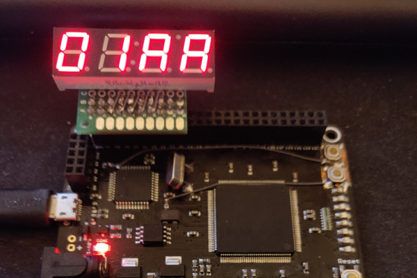
Looking around at the personal computing markets in modern times, there seem to be a lot of choices in the market. In reality, though, almost everything runs on hardware from a very small group of companies, and software is often available across platforms. This wasn’t the case in the personal computing boom of the 70s and 80s, where different computers were wildly different in hardware and even architecture. The Cosmac ELF was one of the more interesting specimens from this era, and this one has been meticulously reproduced on an FPGA.
The original hardware was based on an RCA 1802 microprocessor and had a rudimentary (by today’s standards) set of switches and buttons as the computer’s inputs. It was low cost, even for the time, but was one of the first single-board computers available. This recreation is coded in SpinalHDL and the simplicity of the original hardware makes it relatively easy to understand. The FPGA is cycle-accurate to the original hardware, too, which makes it nearly perfect even without any of the original hardware.
Embarrassing confession time: I never learned my multiplication tables in grade school. Sure, I had the easy tables like the twos and the fives down, but if asked what 4 x 7 or 8 x 6 was, I’d draw a blank. As you can imagine, that made me a less than stellar math student, and I was especially handicapped on time-limited tests with lots of long multiplication problems. The standard algorithm is much faster when you’ve committed those tables to memory, as I discovered to my great woe.
I was reminded of this painful memory as I watched Charles Lohr’s 2019 Supercon talk on the usefulness and flexibility of lookup tables, or LUTs, and their ability to ease or even completely avoid computationally intensive operations. Of course most LUT implementations address problems somewhat more complex than multiplication tables, but they don’t have to. As Charles points out, even the tables of sines and logarithms that used to populate page after page in reference books have been ported to silicon, where looking up the correct answer based on user input is far easier than deriving the answer computationally.
Yes, this is a Minecraft server all thanks to LUTs.
One of the most interesting examples of how LUTs can achieve the seemingly impossible lies in an old project where Charles attempted to build a Minecraft server on an ATMega168. Sending chunks (the data representations of a portion of the game world) to clients is the essential job of a Minecraft server, and on normal machines that involves using data compression. Rather than trying to implement zlib on an 8-bit microcontroller, he turned to a LUT that just feeds the raw bytes to the client, without the server having the slightest idea what any of it means. A similar technique is used by some power inverters, which synthesize sine wave output by feeding one full cycle of values to a DAC from a byte array. It’s brute force, but it works.
Another fascinating and unexpected realization is that LUTs don’t necessarily have to be software. Some can be implemented in completely mechanical systems. Charles used the example of cams on a shaft; in a car’s engine, these represent the code needed to open and close valves at the right time for each cylinder. More complicated examples are the cams and gears once found in fire control computers for naval guns, or the programming cards used for Jacquard looms. He even tips his hat to the Wintergatan marble machine, with its large programming drum and pegs acting as a hardware LUT.
I found Charles’ talk wide-ranging and fascinating. Originally I thought it would be an FPGA-heavy talk, but he didn’t actually get to the FPGA-specific stuff until the very end. That worked out fine, though — just hearing about all the cool problems a LUT can solve was worth the price of admission.
And for the curious, yes, I did eventually end up memorizing the multiplication tables. Oddly, it only clicked for me after I started playing with numbers and seeing their relationships using my first calculator, which ironically enough probably used LUTs to calculate results.
Networked cameras keep making the news, and not in the best of ways. First it was compromised Ring accounts used for creepy pranks, and now it’s Xiaomi’s stale cache sending camera images to strangers! It’s not hard to imagine how such a flaw could happen: Xiaomi does some video feed transcoding in order to integrate with Google’s Hub service. When a transcoding slot is re-purposed from one camera to another, the old data stays in the buffer until it is replaced by the new camera’s feed. The root cause is probably the same as the random images shown when starting some 3D games.
Python is Dead, Long Live Python
Python 2 has finally reached End of Life. While there are many repercussions to this change, the security considerations are important too. The Python 2 environment will no longer receive updates, even if a severe security vulnerability is found. How often is a security vulnerability found in a language? Perhaps not very often, but the impact can be far-reaching. Let’s take, for instance, this 2016 bug in zipimport. It failed to sanitize the header of a ZIP file being processed, causing all the problems one would expect.
It is quite possible that because of the continued popularity and usage of Python2, a third party will step in and take over maintenance of the language, essentially forking Python. Unless such an event happens, it’s definitely time to migrate away from Python2. Continue reading “This Week In Security: Camera Feeds, Python 2, FPGAs”→
With open source software, we’ve grown accustomed to a certain level of trust that whatever we are running on our computers is what we expect it to actually be. Thanks to hashing and public key signatures in various parts in the development and deployment cycle, it’s hard for a third party to modify source code or executables without us being easily able to spot it, even if it travels through untrustworthy channels.
Unfortunately, when it comes to open source hardware, the number of steps and parties involved that are out of our control until we have a final product — production, logistics, distribution, even the customer — makes it substantially more difficult to achieve the same peace of mind. To make things worse, to actually validate the hardware on chip level, you’d ultimately have to destroy it.
On his talk this year at the 36C3, [bunnie] showed a detailed insight of several attack vectors we could face during manufacturing. Skipping the obvious ones like adding or substituting components, he’s focusing on highly ambitious and hard to detect modifications inside an IC’s package with wirebonded or through-silicon via (TSV) implants, down to modifying the netlist or mask of the integrated circuit itself. And these aren’t any theoretical or “what if” scenarios, but actual possible options — of course, some of them come with a certain price tag, but in the end, with the right motivation, money is only a detail.
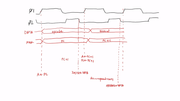
Usually, when you think of designing — or recreating — a CPU on an FPGA, you assume you’ll have to use Verilog or VHDL. There are other options, as well, but those are the biggest two players in FPGA configuration. [Robert Baruch] has a multipart series where he uses nMigen — a Python toolbox — to recreate a 6800 CPU like the one used in many vintage video games and pinball machines.
Unlike some tools that try to convert software written in some language to an FPGA configuration, nMigen uses Python as a scripting language to create code in FHDL. This is similar in concept to VHDL or Verilog, but gives up the event-driven paradigm, opting instead to allow designers to explicitly call out synchronous and combinatorial logic.
Well, this is it. The end of the decade. In a few days the 2010s will be behind us, and a lot of very smug people will start making jokes on social media about how we’re back in the “Roaring 20s” again. Only this time around there’s a lot more plastic, and drastically less bathtub gin. It’s still unclear as to how much jazz will be involved.
Around this time we always say the same thing, but once again it bears repeating: it’s been a fantastic year for Hackaday. Of course, we had our usual honor of featuring literally thousands of incredible creations from the hacking and making community. But beyond that, we also bore witness to some fascinating tech trends, moments that could legitimately be called historic, and a fair number of blunders which won’t soon be forgotten. In fact, this year we’ve covered a wider breadth of topics than ever before, and judging by the record setting numbers we’ve seen in response, it seems you’ve been just as excited to read it as we were to write it.
To close out the year, let’s take a look at a few of the most popular and interesting stories of 2019. It’s been a wild ride, and we can’t wait to do it all over again in 2020.