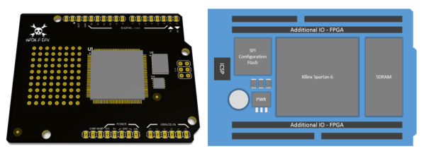
Giving The VirtualBoy A VGA Out

Nintendo’s VirtualBoy – the odd console-inside-a-pair-of-goggles  and arguable ancestor of Nintendo’s 3DS – was a marvelous piece of technology for its time. In a small tabletop unit, you were able to play true 3D video games at an impressive 384 x 224 pixel resolution. Of course the VirtualBoy was a complete failure, but that doesn’t mean hardware tinkerers are leaving this wonderful system to video game collectors. [furrtek] has been playing around with his VirtualBoy and managed to add VGA out.

As a 3D system with two displays, any sort of video out was rightfully ignored by the VirtualBoy system designers. Still, [furrtek] wanted some sort of video out on his system, so he began poking around with a small FPGA board to generate some VGA signals.

The two displays inside the VirtualBoy aren’t your normal LCD display – as seen in this iFixit teardown. they’re really two linear LED arrays that generate a single line of 244 pixels, with mirrors scanning the line in the in the Y axis. These LED arrays are controlled by the VirtualBoy CPU through a series of shift registers, and by carefully tapping the lines of each LED array, [furrtek] was able to copy all the image data into the RAM of an FPGA.

After stuffing an XESS XULA-200 FPGA board inside the case of his VirtualBoy, [furrtek] wired up a few resistors for a DAC and installed a VGA out port on the underside of his console. Everything worked the first time he powered it up, and he began playing his VirtualBoy on his big screen TV.

Because [furrtek] is only reading one of the VirtualBoy’s displays, all the 3D data – and the main feature of the VirtualBoy – is lost when it’s displayed on a TV. 3D TVs do exist, though, and we’d love to see an improved version of this that captures data from both of the VirtualBoy displays.

You can see [furrtek]’s video of his mod in action below.

Continue reading “Giving The VirtualBoy A VGA Out”

Camera-based Touchscreen Input Via An FPGA

piano-hero-uses-camera-based-touch-input

[Chonggang Li] wrote in to share a link to the final project he and [Ran Hu] built for their embedded systems class. It’s called Piano Hero and uses an FPGA to implement a camera-based touch screen system.

All of the hardware used in the project is shown above. The monitor acts as the keyboard, using an image produced by the FPGA board to mark the locations of each virtual key. It uses a regular VGA monitor so they needed to find some way to monitor touch inputs. The solution uses a camera mounted above the screen at an obtuse angle. That is to say, the screen is tilted back just a bit which allows the images on it to be seen by the camera. The FPGA board processes the incoming image, registering a key press when your finger passes between the monitor and the camera. This technique limits the input to just a single row of keys.

This should be much simpler than using a CCD scanner sensor, but that one can track two-dimensions of touch input.

Continue reading “Camera-based Touchscreen Input Via An FPGA”

Hackaday Links: Sunday, May 19th, 2013

hackaday-links-chain

Laser cutter owners may find this online box design tool which [Jon] built quite useful. It’s got a few more joint options than the Inkscape box design add-on does.

Apparently the US Navy has the ability to bring down drones in a flaming pile of laser-caused death. [Thanks Joshua]

[Michail] has been working on a transistor-based full adder. He’s posted a Spice simulation if you want to learn about the design.

Turn your crystal clear LED bodies into diffuse ones using a wooden dowel, power drill, and sandpaper. The results look better than what we’ve accomplished by hand. [Thanks Vinnie]

Play your favorite Atari Jaguar games on an FPGA thanks to the work [Gregory Estrade] did to get it running on a Stratix-II board. You can pick up the VHDL and support tools in his repo. If you’re just curious you can watch his demo vid.

Members of Open Space Aarhus — a hackerspace in Risskov, Denmark — have been playing around with a bunch of old server fans. They made a skirtless hovercraft by taping them together and letting them rip. Too bad it can’t carry its own power supply

Here’s another final project from that bountiful Cornell embedded systems class. This team of students made a maze game that forms the maze by capturing walls drawn on a white board.

And finally, here’s a unique chess board you can build by raiding your parts bin. [Tetris Monkey] made the board from the LCD screen of a broken monitor. The playing pieces are salvaged electronics (like big capacitors) against corroded hardware (like nuts and bolts). We think it came out just great!

Homebrew GPS Gets ±1 Meter Resolution With A Raspberry Pi

GPS

We’ve been following the work of [Andrew Holme] and his homebrew GPS receiver for a while now. A few years ago, [Andrew] built a four-channel GPS receiver from scratch, but apparently that wasn’t enough for him. He expanded his build last year to track up to eight satellites, and this month added a Raspberry Pi for a 12-channel, battery-powered homebrew GPS receiver that has an accuracy of about 3 feet.

The Raspi is attached to an FPGA board that handles the local oscillator, real-time events, and tracks satellites automatically. The Pi handles the difficult but not time-critical math through an SPI interface. Because the Pi is attached to the FPGA through an SPI interface, it can also load up the FPGA with even more custom code, potentially turning this 12-channel receiver into a 16- or 18-channel one.

An LCD display attached to the FPGA board shows the current latitude, longitude, and other miscellaneous data like the number of satellites received. With a large Li-ion battery, the entire system can be powered for about 5 hours; an impressively portable GPS system that rivals the best commercial options out there.

HDMI Color Processing Board Used As An FPGA Dev Board To Mine Bitcoins

fpga-eeColor-bitcoin-mining

The blue board seen above is the guts of a product called the eeColor Color3. It was designed to act as a pass-through between your television and HDMI source device. It boasts the ability to adjust the color saturation to suit any viewing conditions. But [Taylor Killian] could care less about what the thing was made for, he tore it open and used the FPGA inside for his own purposes.

The obvious problem with this compared to a proper dev board is that the pins are not all broken out in a user-friendly way. But he got his hands on it for free after a mail-in-rebate (you might find one online for less than $10 if you’re lucky) and it’s got an Altera Cyclone IV chip with 30k (EP4CE30F23C6N) gates in it so he’s not complaining. The first project he took on with his new toy was to load up an open source Bitcoin mining program. The image above shows it grinding away at 15 megahashes per second while consuming only 2.5 watts. Not bad. Now he just needs to make a modular rack to hold a mining farm.

Playing Meat Boy On An FPGA

We usually look at these FPGA University projects and think how much fun it must have been to get credit for the work. But in this case we can’t image the grind it must have been to implement the game mechanics of Meat Boy in an FPGA. See how well it came out in the clip after the break.

Remember that with an FPGA you’re basically building hardware devices by using code. The Reddit discussion of the project sheds some light on where to start (and even shares the source code). The Altera DE2 is pushing the game to a monitor using SXGA at 60Hz. The map is laid out as a collection of 32×32 tiles, each represented by 2 bits in memory. [SkipToThe3nd] does go into detail about how the physics work but we can’t even begin to paraphrase that part of the discussion.

The game being cloned here is Meat Boy, the Flash game predecessor to Super Meat Boy. If you’ve never heard of the title we’d suggest watching Indie Game: The Moviea documentary which follows several independent game developers as they try to get their titles to market.

Continue reading “Playing Meat Boy On An FPGA”

Building New, Weird CPUs In FPGAs

CPU

The popularization of FPGAs for the hobbyist market means a lot more than custom LED controllers and clones of classic computer systems. FPGAs are also a great tool to experiment with computer architecture, creating new, weird, CPUs that don’t abide by the conventions the industry has used for 40 years. [Victor] is designing a new CPU that challenges the conventions of how to access different memory locations, and in the process even came up with a bit of example code that runs on an ARM microcontroller.

Most of the time, the machine code running on your desktop or laptop isn’t that interesting; it’s just long strings of instructions to be processed linearly. The magic of a computer comes through comparisons, an if statement or a jump in code, where the CPU can run one of two pieces of code, depending on a value in a register. There is the problem of reach, though: if a piece of code makes a direct call to another piece of code, the address of the new code must fit within an instruction. On an ARM processor, only 24 bits are available to encode the address, meaning a jump in code can only go 16 MB on either side of its call. Going any further requires more instructions, and the performance hit that comes along with that.

[Victor] decided a solution to this problem would be to create a bit of circuitry that would be a sliding window to store address locations. Instead of storing the literal address for jumps in code, every branch in the code is stored as a location relative to whatever is in the program counter. The result is an easy way to JMP to code very far away in memory, with less of a performance hit.

There’s an implementation for this sliding window token thing [Victor] whipped up for NXP’s ARM Cortex M3 microprocessor, and he’ll be working on an implementation of this concept in a new CPU over on his git.