Reworking Ball Grid Array Circuit Board Components At Home

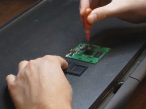
[Jack Gassett] is developing a new breakout board for an FPGA. The chip comes in a ball grid array (BGA) package which is notoriously difficult to solder reliably. Since he’s still in development, the test boards are being assembled in his basement. Of the first lot of four boards, only one is functional. So he’s setting out to rework the bad boards and we came along for the ride.

To reflow the surface mount components he picked up a cheap pancake griddle. The first thing [Jack] does is to heat up the board for about two minutes, then pluck off the FPGA and the FTDI chips using a vacuum tweezers. Next, the board gets a good cleaning with the help of a flux pen, some solder wick, and a regular soldering iron. Once clean, he hits the pads with solder paste from a syringe and begins the soldering process. BGA packages and the solder paste itself usually have manufacturer recommended time and temperature guidelines. [Jack] is following these profiles using the griddle’s temperature controller knob and the timer on an Android phone. In the video after the break you can see that he adjusts the timing based on gut reaction to what is going on with the solder. After cleaning up some solder bridges on the FTDI chip he tested it again and it works!

Continue reading “Reworking Ball Grid Array Circuit Board Components At Home”

LiveLight Is An Expertly Crafted Ambilight Clone

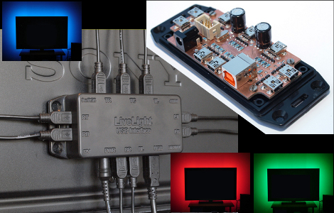
[SunWind] (Edit 2018: who now goes as [nerdaxic]) developed his own version of the Phillips Ambilight system which he is calling LiveLight. We’ve seen more than a few of these hacks, many of them are based around Arduino, and most use LED strip lighting. [Nerdaxic] is using strip lighting as well, but his design is clean and polished quite a bit more than anything else we’ve seen. In our minds this would be welcomed by even the most discriminating of A/V enthusiasts.

He found just the right size of project box and managed to fit everything in on a nicely milled PCB. The enclosure itself has also been milled to allow the mini USB B connectors for each of the nine RGB LED strips. But he didn’t stop there, the top of the enclosure has labels milled into it to help when hooking everything up.

An ATmega32 addresses the LED strips based on data pushed in from a computer. An on-board FTDI chip adds USB connectivity and [nerdaxic] used a hack to rewrite the EEPROM on that chip so that it enumerates with the name “LiveLight USB Interface”. A program called Boblight gathers the data from the currently playing video. You can see the final project in the video embedded after the break.

Continue reading “LiveLight Is An Expertly Crafted Ambilight Clone”

Bitbang IR Remote

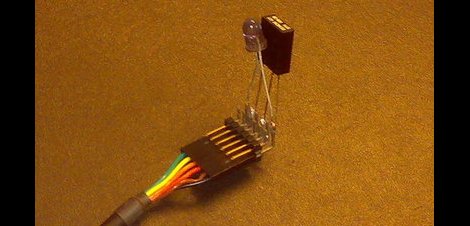
[Albert] has made a few PC IR transmitters and receivers using the traditional connection of RS232 serial, and that is fine, but as we are all aware, not every computer has serial ports standard. Searching though normal USB <> RS232 dongles didn’t meet his requirements. Deciding on making it himself, he whipped up this FTDI bit-bang IR receiver / transmitter.

While FTDI makes a range of chips most (if not all) support a bit-bang mode where you can manually control the IC’s pins. The FTDI chip handles the timing, and when paired up with libFTDI makes it pretty painless to control. The software is a work in progress, but [Albert] already has a driver that connects to LIRC, which lets you control a wide array of remote devices and a test program for carrier generation.

Schematics, source, and a few pages of good information are available on his site.

Broken Laptop Recovered Using An Arduino

We see Arduino boards used in a lot of projects but we’ve never thought of using one as a USB crossover cable. That’s basically what [Jack the Vendicator] did to get his broken laptop running. When his video card stopped working he found himself unable to access the laptop. Newer machines don’t have a serial connector, which could have been used for a serial terminal, so he was at a bit of a loss since neither SSH nor VNC were installed. But he thought he might be able to use the Arduino as a serial terminal connector over USB. He plugged the Arduino into the laptop, and connected a USB serial converter from his desktop computer to the Arduino’s serial pins. In effect he’s just taking advantage of the FTDI chip, translating those signals back into USB on either end. Once he booted the headless laptop it took just a couple of blindly typed commands to get SSH running in order to regain control.

Make A Knitting Machine Print Pixel Art

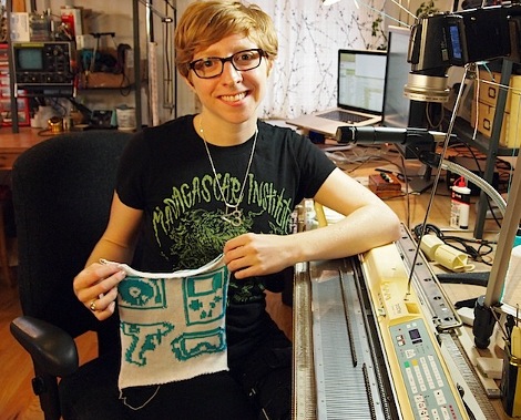
[Becky Stern] shows how to take an old electronic knitting machine and interface it with a computer. After seeing the Brother KH-930E knitting machine in the video after the break it looks like the controls function quite like a CNC milling machine. Patterns can be programmed in and stored on a floppy disk. Since we don’t want to use those anymore (unless they’re hacked as an SD card carriage) it is nice to see that this is how the machine is connected to a computer. Using an altered FTDI cable and a floppy-drive emulator written in Python a blank design file can be saved on the knitting machine, manipulated in the computer to add your own pixel art, then loaded back onto the machine for production. At the very least, it’s interesting to watch the knitting happen, but fans of knitted apparel and geek paraphernalia must be salivating by now.

We’ve never given up our dream to transition from Hack-A-Day to Craft-A-Day, this just fuels the fire for that cause.

Continue reading “Make A Knitting Machine Print Pixel Art”

Propeller Platform Prototyping Board Gets An Upgrade

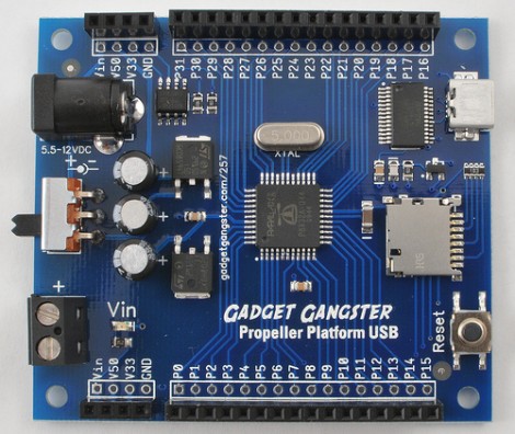
[Nick] over at Gadget Gangster has a new version of his prototyping hardware for Propeller microcontrollers, called the Propeller Platform USB. A little more than a year ago we looked at the last version which was larger, used a DIP processor, and came unassembled. The new version does come assembled because of the migration to surface mount components (which may take some of the fun out of it if you just love soldering kits). This not only reduces the board footprint, but makes room for more goodies. As the name implies, there’s now a mini-USB socket with a USB to UART bridge, a microSD card slot as been added, and the onboard EEPROM has been doubled. This is a nice hardware upgrade but the price has been upgraded by $25 as well. No worries, it’s open source so you can roll your own if you have the parts on hand.

Using An Arduino Or Seeeduino For Its FTDI Chip

We think of the Arduino as a rapid prototyping tool but we never thought of it as an FTDI breakout board before. [Ihsan Kehribar] wrote a quick post to show how it’s done. You’ll find an FTDI chip on Arduino boards that have a USB connector. It’s used to handle the USB communications on one side, and TTL serial communications on the other. The serial pins from the chip are mapped to the UART on the AVR chip, and in turn they appear on the pin headers for easy connections. Just load up a really simple sketch(available from Ihsan’s post) to make sure the processor doesn’t get in the way and you’ve got yourself an FTDI breakout board. If you happen to have a Seeeduino there’s even more functionality as the board has a selector switch that allows you to choose between 5V and 3.3V levels.

This doesn’t hold true to the newest generation of Arduino, as those board have replaced the FTDI chip with an ATmega8U2. That’s basically and ATmega8 with native USB handling… fancy.

[Thanks Marcus]