Radio Shack, despite being gone for a number of years, is still in our cultural consciousness. But do you know Tandy? And did you ever wonder how a leather company that started in 1919 became, briefly, a computer giant? Or even an electronics retailer? [Abort Retry Fail] has the story in three parts, framed with their computers. Well, three parts so far. They are only up to the Tandy 1000.
At first, the company made parts for shoes. But after World War II, they found that catering to leather crafting hobbyists was lucrative. Within a few years, they’d opened stores across the country, making sure that the store managers owned 25% of their stores, even if it meant they had to borrow money from the home office to do so. Meanwhile, Radio Shack was in Boston selling to radio amateurs. By 1935, Radio Shack was a corporation. In 1954, they started selling “Realist” brand equipment, that we would come to know as Realistic.
In 1961, Tandy decided to branch out into other hobby markets, including radio hobbyists. But Radio Shack, dabbling in consumer credit, was sunk with $800,000 of uncollectable consumer credit.
In 1963, Tandy purchased the struggling Radio Shack for $300,000, which was a substantial amount of money in those days. Tandy immediately set about making Radio Shack profitable. Tandy would eventually split into three companies, spinning off its original leather and craft businesses.
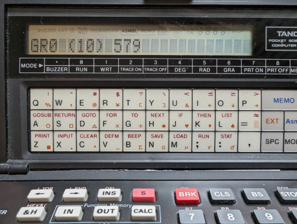
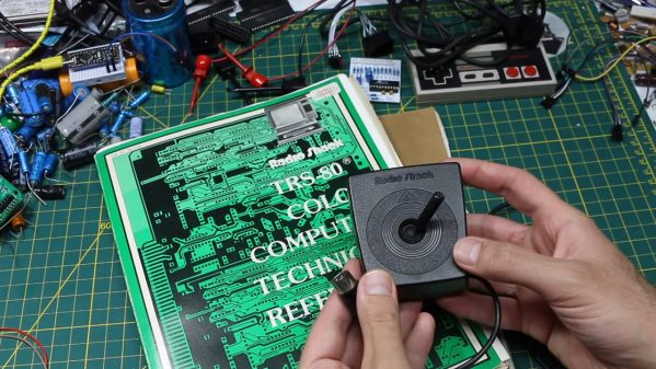
Then came computers. If you are at all interested in the history of early computers, the TRS-80, or any of the other Radio Shack computers, you’ll enjoy the story. It wasn’t all smooth sailing. We can’t wait to read part four, although sadly, we know how the story ends.
We don’t just miss the Radio Shack computers. We loved P-Box kits. Yeah, we know someone bought the brand. But if you visit the site, you’ll see it just isn’t the same.

 The build relies on an