Hackaday Prize Entry: Nuclear Powered Random Number Generator

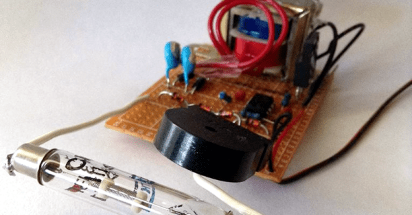
Random number generators come in all shapes and sizes. Some are software based while others, known as true random number generators, are hardware based. These can be created from thermal noise, the photoelectric effect and other methods. But none of these were good enough for [M.daSilva]. He would base his off of the radioactive decay of Uranium 238, and construct a working nuclear powered random number generator.

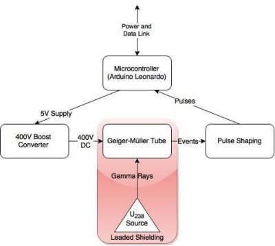
diagram

Because radioactive decay is unpredictable by nature, it makes for an excellent source for truly random data. The process is fairly simple. A piece of old fiestaware plate is used for the radioactive source. Put it in a lead enclosure along with a Geiger tube. Then wire in some pulse shaping circuitry and a microcontroller to count the alpha particles. And that’s about it. [M.daSilva] still has to do some statistical analysis to ensure the numbers are truly random, along with making a nice case for his project. But all in all, it seems to be working quite well.

Be sure to check out the video for quick rundown of [M.daSilva’s] project. If randomness is your thing, make sure you check out entropy harvested from uninitialized RAM, and the story behind the NIST randomness beacon.

Continue reading “Hackaday Prize Entry: Nuclear Powered Random Number Generator”

“Giger Counter” Makes Radiation Detection Surreal

Here’s a quick question: are Geiger and Giger (as in H.R. Giger, designer of the Alien Xenomorph) pronounced the same? The answer is no. Nevertheless, the late artist has had his name mispronounced (for the record, it’s ghee-gur) by many over the years. [Steve DeGroof’s] friend posted a goofy tweet that gave him the inspiration to finally put a skeletal lid on the matter, the Giger Counter.

The innards are a Mightyohm Geiger Counter Kit. The external casing is where the true hack lies in this project, made from a 1:2 scale plastic skeleton model, flexible conduit, and dark metallic spray paint. Only the ribcage, some vertebrae, and part of the skull are used from the model. They are assembled in a delightfully inhuman fashion with some conduit wrapped around it and into the bottom of the ribcage for good measure. After some gluing and spray painting, the LED from the Geiger Counter kit is placed through a drilled hole in the skull while the board sits inside the ribcage. Getting the board in and out can be a little tricky, but it looks like the batteries can be changed without having to pull the whole board out.

Check out the video below to see the Giger Counter. If you want another hack inspired by H.R. Giger’s artistic vision, take a look at this Xenomorph suit we covered.  Or, if you can’t get enough Geiger counters, we’ve featured plenty of cool ones on this site.

Continue reading ““Giger Counter” Makes Radiation Detection Surreal”

LED Matrix Plus Geiger Counter

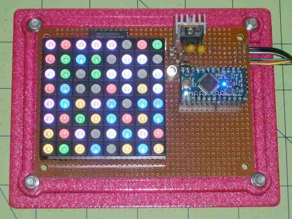
A lot of projects get made because someone just has the parts lying around. In this case, [Ed Nisley] got given a nice 8×8 RGB LED matrix, and needed something to display. [Ed] details the transformation of stuff-lying-on-the-desk into a unique matrix display for a Geiger counter (which he also presumably had sitting around somewhere). The result is a lightshow that’s as random as radioactive decay, and that’s pretty darn random.

img_5583-random-led-dots-circuit-layout-rb-smd-resistorsThe first post covers the hardware layout. It’s build on protoboard, but ends up looking a lot nicer than our projects because [Ed] spent some time hiding the shift-register ICs and row-driver transistors underneath the matrix itself, which was nicely socketed above. A sweet touch is the use of SMT resistors soldered upright underneath the board to save space. Cute.

The second post covers the circuit design, and is worth a look if you’re new to driving many LEDs from a minimum number of microcontroller pins. There are eight rows, and three colors each for eight LEDs per row. Without using shift registers, this would require 8*8*8*8 = way too many pins to control. If you want a worked example of how to do this with just four microcontroller pins, have a look. (Spoiler: cascaded shift registers driven by the AVR’s hardware SPI peripheral.)

The third post starts to flesh out the software. [Ed] settled on seven colors (and off) for the display, so the matrix’s total state can be crammed into just 32 bytes, which fits nicely in even a tiny microcontroller, much less the gargantuan ATmega328. Wrapping this all up in an array of structs and providing a couple of helper functions makes quick work of the software side. The addition of a sync pulse to trigger an oscilloscope at the end of a row is a nice touch.

aware-rm-60-geiger-pulseNext up is the Geiger counter interface software post. When a radioactive decay event is detected, the code reads out the time in milliseconds and uses that as the source of randomness. To whiten the noise, the times are run through a simple hash function: the Jenkins hash (link). This hash function was new to us and seems pretty useful for quick-and-dirty microcontroller applications.

The last post details pre-loading the matrix on startup and running a test sequence that blinks each LED to make sure they’re all working. Using a single random value to seed a software pseudo-random number generator ensures that it will (almost) never start off with the same display twice.

Phswew! That’s a lot of well-documented writeup of a well-polished project! Hope it inspires you to dig out something cool from your junk drawer and build.

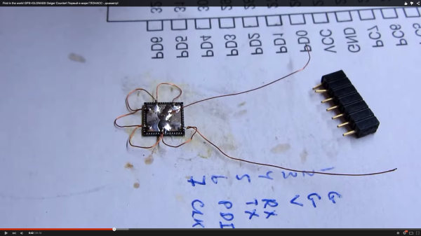
A Deadbugged GPS/GLONASS/Geiger Counter

So you think you’re pretty good at soldering really tiny parts onto a PCB? You’re probably not as good as [Shibata] who made a GPS/GLONASS and Geiger counter mashup deadbug-style with tiny 0402-sized parts.

The device uses an extremely small GPS/GLONASS receiver, an AVR ATxmega128D3 microcontroller, a standard Nokia phone display and an interesting Geiger tube with a mica window to track its location and the current level of radiation. The idea behind this project isn’t really that remarkable; the astonishing thing is the way this project is put together. It’s held together with either skill or prayer, with tiny bits of magnet wire replacing what would normally be PCB traces, and individual components making up the entire circuit.

While there isn’t much detail on what’s actually going on in this mess of solder, hot glue, and wire, the circuit is certainly interesting. Somehow, [Shibata] is generating the high voltage for the Geiger tube and has come up with a really great way of displaying all the relevant information on the display. It’s a great project that approaches masterpiece territory with some crazy soldering skills.

Thanks [Danny] for sending this one in.

Continue reading “A Deadbugged GPS/GLONASS/Geiger Counter”

Artist Inadvertently Builds Hodoscope

A Hodoscope is an instrument used to determine the trajectory of charged particles. It’s built out of a three-dimensional matrix of particle detectors – either PIN diodes or Geiger tubes – arranged in such a way that particles can be traced along coincident detectors, revealing their trajectory.

This is not a hodoscope. It’s a chandelier. This chandelier is made of 92 individual Geiger tubes, each connected to a single LED fixture and a speaker. When a charged particle flies through the room and hits a Geiger tube, the light fixture lights up, a ‘click’ plays on the speaker, and the entire room is enveloped in light for a short moment in time. If, however, that charged particle continues on to another Geiger tube, the trajectory of the particle can be deduced.

The purpose of the installation – beside just being art or something – is to show the viewer sources of radiation and normal levels of radioactivity due to terrestrial and cosmic sources. Of course the spacing of these detectors is rather large – it’s made to fit in a gallery – and there is no connection between the detectors, making a coincident circuit impossible. If you want a real hodoscope, here you go.

This installation can be seen at the Burchfield Penney Art Center in Buffalo, NY through April 12. If you’re in the area, go there and eat a banana. Video below. Thanks [David] for the tip.

Continue reading “Artist Inadvertently Builds Hodoscope”

Global Radiation Monitoring Network Update

Things have been busy at Global Radiation Monitoring Network Central Command. As a semifinalist in the Hackaday Prize, project creator [Radu Motisan] has quite a bit of work to do. He’s not slacking off either. With 33 project logs (and counting), [Radu] has been keeping us up to date with his monitoring network and progress on uRADMonitor , the actual monitoring hardware.

[Radu’s] latest news is that he’s ready to go into production with model A of the uRADMonitor. Moving from project to production can be an incredible amount of work due to sourcing parts, setting up assembly houses, and dealing with any snags that come up along the way. We’re sure [Radu] can handle it, though.

The network of uRADMonitors is also growing. A new monitor was just installed in Prescott, Arizona. This is the 10th unit in the USA.  You can view the map, data, and graphs of global radiation live on the uRADMonitor website.


SpaceWrencherThe project featured in this post is a semifinalist in The Hackaday Prize.

A Geiger Counter For An Off-Road Apocalypse Vehicle

prog2

If the world comes to an end, it’s good to be prepared. And let’s say that the apocalypse is triggered by a series of nuclear explosions. If that is the case, then having a Geiger counter is a must, plus having a nice transport vehicle would be helpful too. So [Kristian] combined the two ideas and created his own Geiger counter for automotive use just on the off chance that he might need it one day.

It all started with a homemade counter that was fashioned together. Then a display module with a built-in graphics controller that was implemented to show all kinds of information in the vehicle. This was done using a couple of optocouplers as inputs. In addition, a CAN bus interface was put in place. As an earlier post suggests, the display circuit was based on a Microchip 18F4680 microcontroller. After that, things kind of got a little out of control and the counter evolved into more of a mobile communications center; mostly just because [Kristian] wanted to learn how those systems worked. Sounds like a fun learning experience! Later the CPU and gauge was redesigned to use low-quiescent regulators. A filtering board was also made that could kill transients and noise if needed.

The full project can be seen on [Kristian]’s blog.