Can you generate VGA and handle a PS/2 keyboard with a Cortex-M4 in Rust? That’s precisely what [theJPster] wanted to find out with Monotron, a 1980s style home computer programmed in pure Rust.
In order to run embedded Rust without a working operating system, some tools are necessary: an LLVM back-end for generating machine code, a target file for specifying memory sizes and other configs, and a pre-compiled libcore as a substitute for a compiler when running an operating system. Rust takes the place of C running on top of the board support package (BSP) and hardware abstraction layer (HAL), and peripheral access crates (PACs) that specify the hardware and allow the code to be portable across different chips.
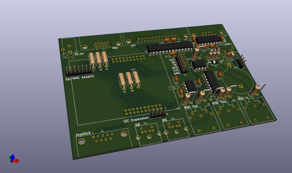
The implementation generates a 800 x 600 VGA video signal at 60 Hz, displays text on a 48 character by 36 line display, displays color graphics using color lookup (stored in flash memory), and runs applications that take less than 24 KiB for all data. Monotron also generates 8-bit audio with PWM and sports a synthesizer that uses a three-channel wavetable allowing it to make sounds with square waves, sine waves, sawtooth waves, and create white noise.
So far, the Monotron has been able to work with an Atari joystick, a PS/2 keyboard, and has outputs to VGA, MIDI, SD card, and audio. Next up for the Monotron: writing a programming language (tentatively named Monotronian), adding support for Sega Megadrive pads, displaying sprites, and many more exciting developments.
Continue reading “A DIY Retrocomputer Programmed In Pure Rust”