It is sort of the American dream: start a company in your garage and have it get crazy big. After all, Steve Jobs, Bill Gates, and even Bill Hewlett and Dave Packard did it. Seems hard to do these days, though. However, one ham radio company that has been pushing the edge of software defined radio appears to be well on the way to becoming more than its roots. FlexRadio has teamed with Raytheon to undertake a major project for the United States Air Force.
The Air Force has given Raytheon and FlexRadio $36 million to develop an HF radio based on the existing SmartSDR/Flex-6000. ARRL news reports quote FlexRadio’s CEO as saying that the investment in the military radios will pay dividends to the firm’s ham radio customers.
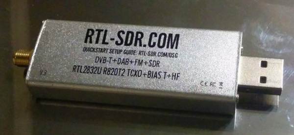
We usually think of the RTL-SDR as a low-cost alternative to a “real” radio, but this incredible project spearheaded by [Rodrigo Freire] shows that the two classes of devices don’t have to be mutually exclusive. After nearly 6 months of work, he’s developed and documented a method to integrate a RTL-SDR Blog V3 receiver directly into the Yaesu FT-991 transceiver.
The professional results of the hack are made possible by the fact that the FT-991 already had USB capability to begin with. More specifically, it had an internal USB hub that allowed multiple internal devices to appear to the computer as a sort of composite device.
Unfortunately, the internal USB hub only supported two devices, so the first order of business for [Rodrigo] was swapping out the original USB2512BI hub IC with a USB2514BI that offered four ports. With the swap complete, he was able to hang the RTL-SDR device right on the new chip’s pins.
Of course, that was only half of the battle. He had a nicely integrated RTL-SDR from an external standpoint, but to actually be useful, the SDR would need to tap into the radio’s signal. To do this, [Rodrigo] designed a custom PCB that pulls the IF signal from the radio, feed it into an amplifier, and ultimately pass it to the SDR. The board uses onboard switches, controlled by the GPIO ports on the RTL-SDR Blog V3, for enabling the tap and preamplifier.
Somehow [hvde] wound up with a CB radio that does AM and SSB on the 11 meter band. The problem was that the radio isn’t legal where he lives. So he decided to change the radio over to work on the 6 meter band, instead.
We were a little surprised to hear this at first. Most radio circuits are tuned to pretty close tolerances and going from 27 MHz to 50 MHz seemed like quite a leap. The answer? An Arduino and a few other choice pieces of circuitry.
Software-defined radios or SDRs have provided a step-change in the way we use radio. From your FM broadcast receiver which very likely now has single-application SDR technology embedded in a chip through to the all-singing-all-dancing general purpose SDR you’d find on an experimenter’s bench, control over signal processing has moved from the analogue domain into the digital. The possibilities are limitless, and some of the old ways of building a radio now seem antiquated.
[Pete Juliano N6QW] is an expert radio home-brewer of very long standing, and he’s proved there’s plenty of scope for old-fashioned radio homebrewing in an SDR with his RADIG project. It’s an SDR transceiver for HF which does all the work of quadrature splitting and mixing with homebrewed modules rather than the more usual technique of hiding it in an SDR chip. It’s a very long read in a diary format from the bottom up, and what’s remarkable is that he’s gone from idea to working SDR over the space of about three weeks.
So what goes into a homebrew SDR? Both RF preamplifier, filters, and PA are conventional as you might expect, switched between transmit and receive with relays. A common transmit and receive signal path is split into two and fed to a pair of ADE-1 mixers where they are mixed with quadrature local oscillator signals to produce I and Q that is fed to (or from in the case of transmit) a StarTech sound card. The local oscillator is an Si5351 synthesiser chip in the form of an SDR-Kits USB-driven module, and the 90 degree phased quadrature signals are generated with a set of 74AC74 flip-flops as a divider.
Running the show is a Raspberry Pi running Quisk, and though he mentions using a Teensy to control the Si5351 at the start of his diary it seems from the pictures of the final radio that the Pi has taken on that work. It’s clear that this is very much an experimental radio as it stands with wired-together modules on a wooden board, so we look forward to whatever refinements will come. This has the feel of a design that could eventually be built by many other radio amateurs, so it’s fascinating to be in at the start.
If I and Q leave you gasping when it comes to SDR technology, maybe we can help.
Of all the images that amateur radio conjures up, the great outdoors doesn’t usually figure heavily. People seem to think hams sit in a dark room at a desk heavy with radio gear, banging out Morse code into late into the night and heedless of the world outside the window. All of which sort of sounds like hard-core gaming, really.
And while that image certainly applies in a lot of cases, hams do like to get out and about at least once a year. That day is upon us with the 2019 Amateur Radio Field Day. Hams across North America reserve the fourth full weekend of each June to tear themselves out of their shacks and get into the world to set up operations in some kind of public venue, generally a park or other green space. Part cookout, part community outreach, and part slumber party – it lasts all weekend and goes around the clock – hams use field day as a chance to show the general public where amateur radio really shines: real-time worldwide communications under austere conditions.
It’s also a chance to get folks excited about getting their license, with many Field Day locations hosting “Get on the Air” stations so that unlicensed folks can try making a contact under the supervision of a licensed operator. Licensed but underequipped hams also get the chance to spin the knobs on someone else’s gear, and maybe line up that first rig purchase. And there are plenty of opportunities to learn about new modes as well, such as FT8 and WSPR. As an example your scribe is looking for some guidance on getting started with APRS, the automated packet reporting system that’s used for things like high-altitude balloon tracking.
If you have any interest at all in learning how to properly operate radio equipment, you owe it to yourself to track down the nearest Field Day location and stop by. The American Radio Relay League (ARRL) has a ton of Field Day information, from a map to locate the 1500 Field Day sites to rules for the contests that will be run that weekend to guides for setting up and operating an effective Field Day setup. There will be 40,000 hams out there this year, and they’d all be thrilled if you drop by and ask a few questions.
This is an exciting day for me — we finally get to build some ham radio gear! To me, building gear is the big attraction of amateur radio as a hobby. Sure, it’s cool to buy a radio, even a cheap one, and be able to hit a repeater that you think is unreachable. Or on the other end of the money spectrum, using a Yaesu or Kenwood HF rig with a linear amp and big beam antenna to work someone in Antartica must be pretty cool, too. But neither of those feats require much in the way of electronics knowledge or skill, and at the end of the day, that’s why I got into amateur radio in the first place — to learn more about electronics.
To get my homebrewer’s feet wet, I chose perhaps the simplest of ham radio projects: dummy loads. Every ham eventually needs a dummy load, which is basically a circuit that looks like an antenna to a transmitter but dissipates the energy as heat instead of radiating it an appreciable distance. They allow operators to test gear and make adjustments while staying legal on emission. Al Williams covered the basics of dummy loads a few years back in case you need a little more background.
We’ll be building two dummy loads: a lower-power one specifically for my handy talkies (HTs) will be the subject of this article, while a bigger, oil-filled “cantenna” load for use with higher power transmitters will follow. Neither of my designs is original, of course; borrowing circuits from other hams is expected, after all. But I did put my own twist on each, and you should do the same thing. These builds are covered in depth on my Hackaday.io page, but join me below for the gist on a good one: the L’il Dummy.
Antennas come in many shapes and sizes, with a variety of characteristics making them more or less suitable for various applications. The average hacker with only a middling exposure to RF may be familiar with trace antennas, yagis and dipoles, but there’s a whole load more out there. [Eric Sorensen] is going down the path less travelled, undertaking the build of a self-tuning magnetic loop antenna.
[Eric]’s build is designed to operate at 100W on the 20 meter band, and this influences the specifications of the antenna. Particularly critical in the magnetic loop design is the voltage across the tuning capacitor; in this design, it comes out at approximately 4 kilovolts. This necessitates the careful choice of parts that can handle these voltages. In this case, a vacuum variable capacitor is used, rated to a peak current of 57 amps and a peak voltage of 5 kilovolts.
The magnetic loop design leads to antenna which is tuned to a very narrow frequency range, giving good selectivity. However, it also requires retuning quite often in order to stay on-band. [Eric] is implementing a self-tuning system to solve this, with a controller using a motor to actuate the tuning capacitor to maintain the antenna at its proper operating point.
If you’re unfamiliar with magnetic loop builds, [Eric]’s project serves as a great introduction to both the electrical and mechanical considerations inherent in such a design. We’ve seen even more obscure designs though – like these antennas applied with advanced spray techniques.