Where you might see a can, [Adam Kumpf] sees a robot. [Adam’s] robot (named [Canny]) doesn’t move around, but it does have expressive eyebrows, multicolored eyes, and a speaker for a mouth. What makes it interesting, though, is the fact that it receives audio commands via the headphones it wears. You can see [Canny] in action in the video below.
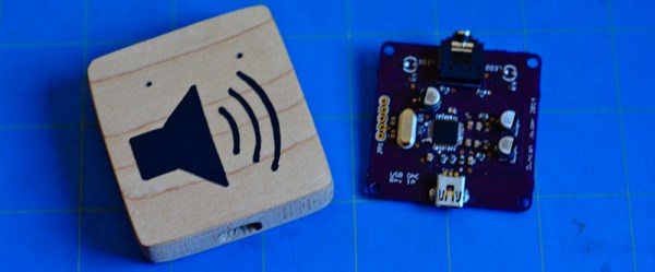
The headphones couple audio tones to [Canny’s] microphone using AFSK (audio frequency shift keying). [Canny] uses an opamp to bring the microphone level up and then uses a 567 PLL IC to decode the audio tones. [Adam] selected two clever frequencies for the mark and space (12345 Hz and 9876 Hz). In addition to being numerically entertaining, the frequencies are far enough apart to be easy to detect, pass through the headphones with no problem, and are not harmonically related.
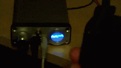 Since she was going with an oscilloscope style vector scan rather than the raster scan the screen electronics were originally designed for, [ErikaFluff] had to create her own horizontal and vertical deflection circuits. Horizontal scan is created by a 555 timer generating a sawtooth wave at 75 Hz. Vertical deflection is via an LM386 driving a hand wound impedance matching transformer. The high voltage flyback transformer and its associated driver circuit were kept from the original CRT, though repackaged to make them as small as possible.
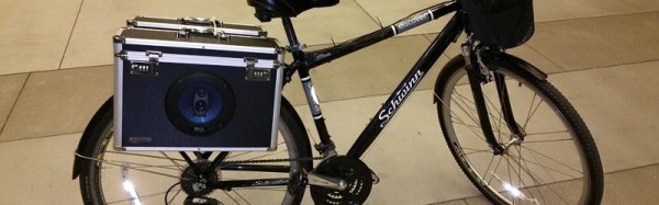
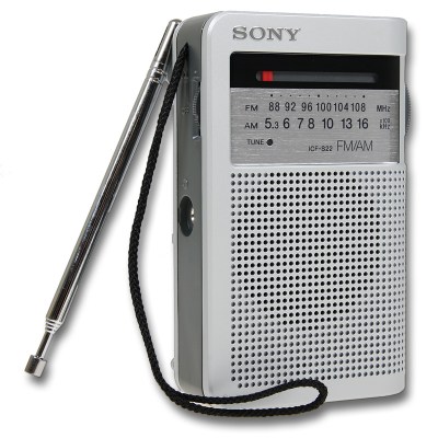 [sswanton] started out by disassembling the ultra-inexpensive, old-school, battery-powered Sony ICF-S22 radio specified by the class. The stock case was discarded as he would have to make a new one that fits onto the bike’s handlebars. Plywood makes up majority of the frame while the cover is black acrylic. Getting the acrylic bent required heating to 160 degrees so that it could be bent around a form [sswanton] created specifically for this project. A few cutouts in the case allows the rider to access the volume and tuning knobs.