DIY Amplifier Minder Turns Off Your Stereo When You Forget

arduino_receiver_minder

[zmashiah] has a nice Nova tube amplifier in his living room, and he often forgets to turn it off once he’s done listening to music. He feels guilty when this happens, as it not only shortens the lifespan of his stereo, but it’s not exactly the greenest behavior either. Rather than let his receiver idle any longer, he built a simple device that automatically turns it off when he forgets.

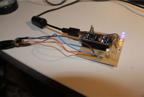
He wired an Arduino to the line level output of the receiver, sampling the audio every two seconds. When five minutes pass without an audio signal, the Arduino sends an IR command to the receiver, turning it off.

He says he’s aware that it might be overkill to use an Arduino for this application, but that he would rather fork out an extra dollar or two instead of spending hours poring over AVR assembly code. While we’re all for efficiency, we can’t exactly argue with that logic – time is money!

[zmashiah] is kind enough to include his schematics as well as the code for his project, so be sure to check it out if you occasionally forget to turn off your IR-enabled appliances.

Prototyping A Bluetooth To IR Remote Control Translator

[James] is one of those guys on a quest to control everything with one device. His tool of choice is an Android phone, which can do quite a lot right out of the box. But he was never satisfied with its lack of IR remote control abilities. He fixed that feature-gap by building a Bluetooth to Infrared translator.

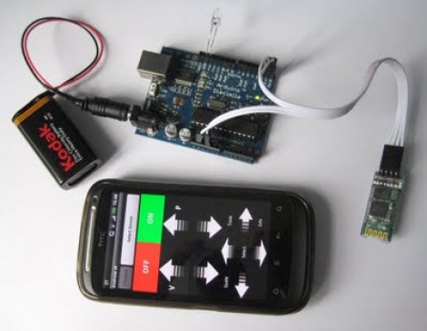
The hardware he used for the prototype is quite simple. A cheap serial Bluetooth modem from eBay lets him connect to his phone. An Arduino board listens for data from the modem and converts incoming commands to flashes on an IR LED. Voila, he can control the tube with his phone.

We love the potential of this hack. The Bluetooth module runs from 3.3V, and reading serial data and flashing an LED is extremely simple. You should be able to use a small uC, say an ATtiny13, and a 3.3V regulator to miniaturize the module. We could see this plugging into the USB port on the back of a TV for power, with a wire extension to put the LED into position. The only shortfall is the inability to turn the TV on remotely when drawing power this way.

Remote codes aren’t particularly large to store either. So this would be pretty easy to extend to full control of all IR-compatible home entertainment devices. You just need a tool to discover the remote control codes.

Continue reading “Prototyping A Bluetooth To IR Remote Control Translator”

How To Decode IR Remote Control Signals With Your PICkit 2

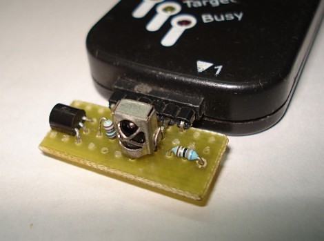
[SpiralBrain] needed to figure out the coding scheme used by an IR remote control so that he could use it with his own project. He built an IR receiver board for the PICkit 2 and figured out how to use some of the Microchip software to measure the timing of the incoming signal.

The hardware’s dead simple; a 38 kHz IR receiver does the heavy lifting by filtering out errant infrared light. When it does detect a signal with the correct frequency the output pin drives the base of a transistor to toggle the input pin on the PICkit 2. The breakout board has a pin header which makes it a snap to detach and store for later use. The PICkit 2 Logic Tool software captures this input, by setting the correct pin as a trigger and choosing a 10 kHz sample rate.

As we discussed in our PIC programming with Linux tutorial, the PICkit 2 really is far superior to its replacement, the PICkit 3. [SpiralBrain] mentions that it is more versatile than the newer version but doesn’t go so far as to tell us whether you can use this hardware with the PICkit 3 or not.

Matchbox-sized Line Following Robot

pocketbot_line_following_robot

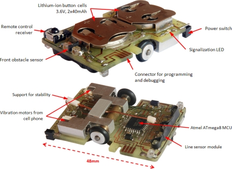
While they are not nearly as complex as their self-navigating brethren, building line following robots is no simple task, especially when they are this small. The creation of [Ondřej Staněk], this matchbox-sized line following robot is quite impressive.

PocketBot’s 48mm x 32mm circuit board also acts as its frame, supporting the wheels, motors, microcontroller and more. The brains of the operation is an ATmega8 microcontroller mounted on the bottom of the bot. A pair of wheels are driven independently using a set of mobile phone vibration motors that power the bot at speeds of up to 0.35 meters per second. Line detection is achieved by using three different IR sensors paired with four IR emitters located at the front end of the bot.

PocketBot also has an IR receiver on its top side, which allows [Ondřej] to control the robot, tweak its parameters, or calibrate its sensors on the fly using an IR remote or his computer.

The PocketBot might not be the absolute smallest line following bot we’ve seen, but it’s pretty darn close!

Continue reading to see PocketBot in action.

Continue reading “Matchbox-sized Line Following Robot”

DIY Wiper Speed Control And Collision Avoidance

ir_sensor_rain_detection

On many new cars, automatic wiper speed control can be had as an upgrade, though most cars do not offer front-end collision prevention at all. [Rishi Hora] and [Diwakar Labh], students at the Guru Tegh Bahadur Institute of Technology in New Delhi, developed their own version of these features, (PDF warning, skip to page 20) which they entered into last year’s Texas Instruments Analog Design Contest. Under the guidance of professors [Gurmeet Singh] and [Pawan Kumar], the pair built the systems using easily obtainable parts, including of course, an MSP430 microcontroller from TI.

The collision prevention system uses a laser emitter and an optical detector to estimate the distance between your car and the vehicle in front of you, sounding an alarm if you are getting too close. In a somewhat similar fashion, the wiper speed control system uses an IR emitter and detector pair to estimate the amount of water built up on the windshield, triggering the wipers when necessary.

While not groundbreaking, the systems would be quite handy during monsoon season in India, and seem easy enough to install in an older vehicle. The only thing we’re not so sure about is pointing lasers at cars in traffic, but there are quite a few available alternatives that can be used to measure distance.

Continue reading to see a video walkthrough and demonstration of both systems.

Continue reading “DIY Wiper Speed Control And Collision Avoidance”

Measuring RPM With Reflective Sensors

[Arao] wanted to measure the RPM of a spinning wheel using parts that he could scavenge from his junk box. A bit of thought led him to build a reflective sensor which can measure the spinning of a wheel (translated).

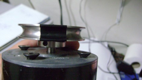
He got his hands on an infrared phototransistor which had been used as part of the remote control for some consumer electronics. Snooping around with his multimeter helped him establish the pin out of the device. By positioning an IR LED inside of a shroud, yet adjacent to the phototransistor, he can measure the intensity of the LED’s light as it is reflected off of nearby surfaces. The pulley seen above has a piece of electrical tape on it. When this passes by the LED, less of the infrared light is reflected and the drop in intensity is picked up by the phototransistor. [Arao] made the system rock-solid by rolling an LM358 op-amp into the circuit. He’s posted the schematic as well as some screen shots from an oscilloscope during testing.

Long-range Canon DSLR Remote Video Trigger

canon_60D_remote_video_trigger

Instructables user [Justin] generally enjoyed shooting video with his Canon 60D DSLR, though there was one small problem. The only way that the camera could be remotely triggered to shoot video was via a small IR remote with a paltry 10 foot range. Even worse, the remote had to be pointed directly at the front of the camera to work at all. To remedy the situation, he decided to rig up his own long-range trigger mechanism.

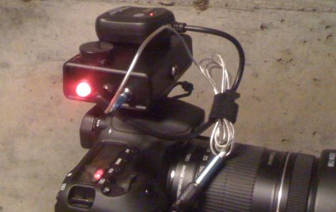
He cobbled together an Arduino with components he had sitting around, mounting it in a project box on top of the camera. A commercially available RF remote shutter release is also mounted on the top of the camera, and wired to the Arduino using a small 2.5mm plug. When he activates the RF remote, it sends a pulse to the Arduino, which in turn sends the appropriate signal to his camera via a small IR LED.

While he readily admits that he could have likely used a much simpler configuration, the Arduino does its job, and he’s quite happy with his solution. We agree with him about the Arduino, but it’s hard to argue with saving money by using components you already have on-hand.