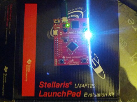
We just got our hands on a Stellaris Launchpad. We had placed an order when the preorder was originally announced, but the marketing folks at TI reached out an offered to send us one a bit sooner and took them up on it. We’ve embedded a quick unboxing video after the break but read on for some info that didn’t make it into that clip.
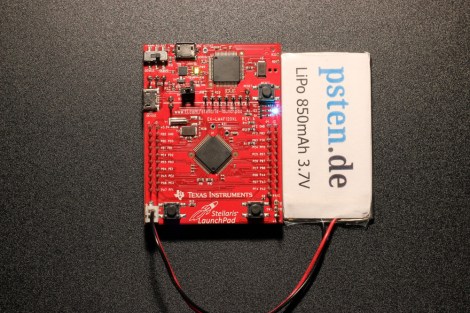
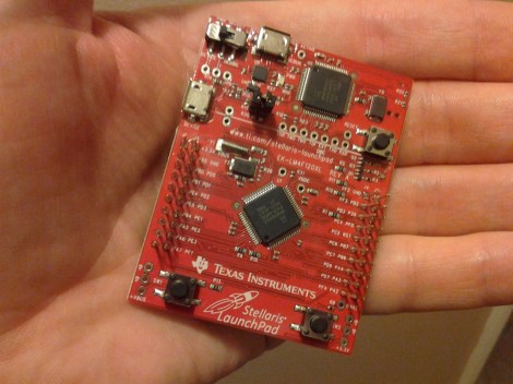
The look and feel of the board and its packaging are almost exactly the same as the MSP430 version of the Launchpad. But why not? After all it worked so well the first time. This board hosts an ARM Cortex-M4 processor. The two buttons on the bottom are user buttons, the one on the upper right is a reset button. The top of the board is the programmer, with a micro USB port for connectivity. The kit also includes about a 2′ cable for this connection. Next to that jack is a switch that selects a power source. You’ll also notice a USB port to the left, this because the processor includes USB functionality, with a free library available from TI. Power can come from the programmer/debugger USB port, or from this device USB port. There are dual pin headers to either side on the face of the board, and pin sockets on the back which break out pins of the processor. Just below the reset button is a RGB LED, and a clock crystal has also been populated just above the chip.
When plugged in via the programmer’s USB port the PWR LED lights up as does the RGB LED. The firmware that ships on the device fades through a range of colors and the user buttons scroll through a set of predefined colors. The device enumerates as: “Bus 002 Device 005: ID 1cbe:00fd Luminary Micro Inc.” on our machine. But if you connect it via the device USB jack it enumerates as: “Bus 001 Device 015: ID 04e8:689e Samsung Electronics Co., Ltd GT-S5670 [Galaxy Fit]”. Interesting.
We have no idea if there are programming tools for flashing the board using a Linux box, but we’ll be trying to figure it out. If you have some info please share it in the comments.
Continue reading “Hands On The Stellaris Launchpad” →
