If you’ve worked with circuit simulation, you may have run into IBIS models. The acronym is input/output buffer information, and while you can do a lot without having to deal with IBIS, knowing about it can help you have a successful simulation.
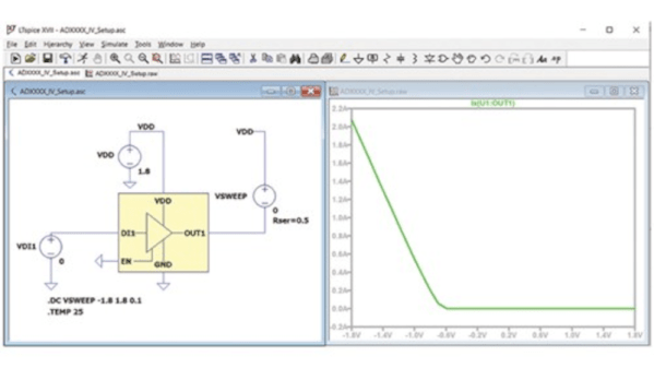
IBIS is an industry-standard format that uses ASCII text to describe voltage versus current and voltage versus time about some device’s digital input and output pins. This allows precise simulation without revealing the device’s internals, which is important to some vendors. The first post of this two-part series talks about what IBIS is and how it got started. The second part explains creating and using LTSpice to create your own IBIS models. It also covers why you might want to do that.
Of course, if you don’t care about revealing the internals of a device, you could just create a Spice simulation. However, many tools will accept both models, so it is useful to know how to produce either kind of model. In fact, to create an IBIS model, you’ll want to use a Spice model to generate the data for the IBIS model, so it is a good bet you’ll have both, even if you choose to only publish the IBIS models.
If you need a refresher on Spice, we have a series. If you prefer using something different, try Micro-Cap 12, which was commercial, but went free a few years ago.