Harnessing The Electrical Power Of Clams

Yes, that is a clam. Yes researchers are using them as batteries. Yes, that quip about the matrix  and clam-Neo that is bubbling up into your temporal lobe is appropriate. While keeping a clam as “happy as a clam” might not necessitate a virtual world, they don’t really produce much electricity either. Researchers were able to siphon almost 29 millijoules over the course of an hour. This was enough to turn their electric motor one quarter of a turn.

Wether you find this kind of biological hacking ethical or not, you’ll probably agree that the following quote is, at least a tiny bit, creepy.

The researchers tried different ways to connect three clams at a time as a collective living battery. A serial circuit boosted the battery’s voltage (electric potential), whereas a parallel circuit increased the current (rate of charge flow) — but the overall electricity available often changed depending on each clam’s health.

This LED Table Really Ties The Room Together

led-matrix-table

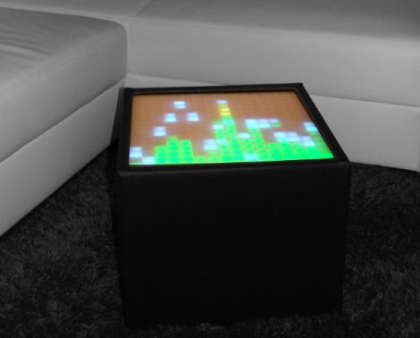
Along with quadrotors, and portable game consoles, one of the hacks we never get tired of seeing is an LED matrix table. [Christian Enchelmaier] wrote in to share his take on the ever popular pixelated furniture, which we think came out pretty well (Translation).

Instead of going for a full-sized coffee table, [Christian] decided to keep things on the smaller scale his first time out, opting for an ottoman/end table nstead. He constructed a 16×16 matrix using RGB LEDs, encapsulating each one in its own “pixel”, as is common with these builds. [Christian] uses an Atmega 128 to run the show, displaying the current time and date, temperature, music visualizations, games, images, along with short videos. He also outfitted the table with an IR receiver so that he can control the table’s display from afar.

As of right now, [Christian] doesn’t have any video of the table in action, but there’s plenty in the way of pictures scattered throughout his build log to keep you busy in the meantime.

Matrix Backpack Was A Fun Design Project

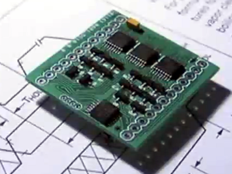
[Greg] is really working on a small scale with his LED Matrix backpack PCB. It’s a toy that he designed as an activity. He constrained himself to a board which would exactly match the outline of an 8×8 bicolor LED matrix package.

What you see here is the side of the PCB which will be facing the underside of the LED dot matrix module. Let’s call this the top of the board. The underside has a CR2032 battery holder which provides enough juice to run the display. Since the matrix is bi-color there’s a slew of pins to drive. [Greg] uses three shift registers for the high side, and sixteen N-channel MOSFETS for the low side. He’s chosen an MSP430G2201 microcontroller which has a nice sleep mode for power conservation. It has no problem driving tri-color animations as seen the clip after the break, but also has an unpopulated clock crystal footprint if you wanted to use it as a timepiece.

Despite the small footprints and cramped board [Greg] still hand soldered all of the components. He even posted a time-lapse of the process in the page linked at the top.

Continue reading “Matrix Backpack Was A Fun Design Project”

Numerous Quiz Buttons Built On The Cheap

[Sprite_TM] was tapped to build a rather large quiz buzzer system. Judging from his past work we’re not surprised that he seemed to have no trouble fulfilling the request. As the system is not likely to be used again (or rarely if it is) he found a way to finish the project that was both quick and inexpensive.

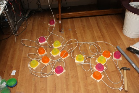
Each buzzer consists of a base, a button (both mechanical and electrical), and a couple of LEDs to indicate who buzzed in first. The mechanical part of the button uses a plastic bowl from Ikea and a wooden dowel surrounded by some pipe insulation. A momentary push switch is glued on the top of that dowel, and the insulation projects above that just a bit. This way it acts as a spring. The Dowel has been sized so that the bowl lip will hit the wooden base just as it clicks the switch.

As you can see, all of the buzzers are interlinked using Ethernet cable. The real trick here is how to read 14 buttons using just one CAT5 cable. This is done with the clever use of a 4×4 button matrix for a total of 16 buttons. The matrix also includes the LEDs for each buzzer. Since CAT5 has four twisted pairs this works out perfectly.

Looking for a more robust system thank this? Here’s a pretty nice one.

Rainbow Board Of Many Ping-pong Balls

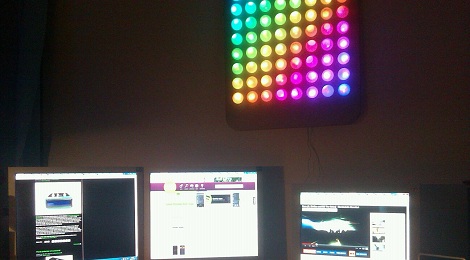
[George] just finished his first project: an 8×8 matrix “Board of Many Ping-Pong Balls” with 64 RGB LEDs. He started this project when he was 14 years old and finished the build over this last Christmas break. We won’t make any presumptions about [George]’s age, but we couldn’t think of a better project to start out on.

For the build, [George] used a Colorduino LED driver shield for his Arduino. This made the wiring simple, but the finished product is where this project really shines. For the base, [George] got a board laser cut at his school and used ping-pong balls to diffuse the LEDs. We’ve seen this many times but with this build there’s a neat way to drill a hole in a ping-pong ball; simply put the drill into reverse. The friction is enough to open the ball up, and the chips of plastic come outside instead of remaining in.

We’re really impressed with [George] and his winter break project. He’s lucky enough to have access to a laser cutter at school, and from a look at his monitor, he’s reading the right websites. You can check out his demo rainbow pattern after the break.

Continue reading “Rainbow Board Of Many Ping-pong Balls”

This Giant Hand Made LED Matrix Must Be Ours!

giant-led-matrix

[Martin] wrote in to share a project his company has been working on for some time, a gigantic 1470 pixel LED wall. The group provides lighting for clubs, parties, etc, and their hand-built LED matrix is always certain to be the hit of the show.

The amazing matrix was designed from the ground up and built by hand in [Martin’s] living room. They designed small 32x32mm “pixel” boards, each of which features 6 PLCC6 RGB LEDs driven by a single WS2801 LED controller. The PCBs were populated by hand and each one was reflowed in a small pizza oven that [Martin] owns. After the pixels were completed, they were attached to aluminum bar and combined to build thirty 70x70cm frames which are connected together to form a giant matrix.

As you can see in the collection of videos below, the display is very impressive. We just hope that they will be compelled to release the schematics for their boards so that we can build one of these in the office.

Continue reading “This Giant Hand Made LED Matrix Must Be Ours!”

Video Display From RGB Strips Makes It Seem So Easy

[Fabien] wrote in to share a link to this RGB video display which he made. He’s got some pretty cool routines that make it more functional than you would think, but first we want to comment on the construction. He used an RGB strip, which makes this look like an incredibly simple build. The strip has a data and power bus running the length of it. You can it into smaller segments, then just solder jumper wires to reconnect the buses. That’s exactly what he did here, making it what must be the fastest method of putting together a display of this size (16×10 pixels).

It’s driven by a Netduino which easily addresses the LPD8806 drivers responsible for the LEDs. It gets input from a computer via Xbee, making it easy to include data from the net, or to push visualizations. The video after the break shows a [Van Gogh] self-portrait. Since 160 pixel resolution wouldn’t do it justice, the visualization software shows a zoomed in portion of the painting which is constantly panning to let you see the entire work. It’s a fabulous effect.

Continue reading “Video Display From RGB Strips Makes It Seem So Easy”