Z80 Testing The 80s Way

According to [MTSI], if you used a Z80 chip back in the 1980s, it almost certainly passed through the sole Fairchild Sentry 610 system that gave it the seal of approval.

The Sentry was big iron for its day. The CPU was a 24-bit device and ran at a blistering 250 kHz. Along with a tape drive and a specialized test bed, it could test Z80s, F8s, and other Mostek products of the day. There was a disk drive, too. The 26-inch platters stored under 10 kilobytes. Despite the relatively low speed of the CPU, the Sentry could test devices running up to 10 MHz, which was plenty for the CPUs it was testing. The actual test interface ran at 11 MHz and used an exotic divider to generate slower frequencies.

According to the post, an informal count of the number of chips in the device came up with around 60,000. That, as you might expect, took a huge power supply, too.

Continue reading “Z80 Testing The 80s Way”

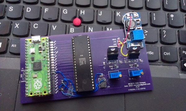
A purple PCB with a Raspberry Pi Pico and an MK3870 mask ROM microcontroller

A 1970s Mask ROM MCU Spills Its Secrets

If you buy any kind of electronic gadget today, chances are it’s powered by a microcontroller with a program stored in its internal flash ROM. That program’s code is often jealously guarded by the manufacturer, who will try their best to make sure you can’t just read back the chip’s contents by using lock bits or some sort of encryption. Things were more laid back in the 1970s and ’80s, when code was stored unencrypted in standard EPROM chips, or, for high-volume applications, in mask ROMs integrated in microcontrollers. Reading back the code of such micros was still very difficult because chips simply didn’t have a way of dumping their contents. [Andrew Menadue] ran into this issue when trying to repair an old HP calculator printer, and had to apply a clever hack to dump the contents of its Mostek MK3870 chip.

The main trick [Andrew] used was one discovered by [Sean Riddle] and explained on his website. It makes use of the fact that the MK3870 has a TEST pin that can be used to disable the mask ROM and load alternative program code directly into the micro’s processing core. By setting up a LOAD instruction pointing at a ROM location and briefly disabling test mode while that instruction is executed, the ROM’s contents can be read out by the externally loaded program.

Simple as this hack may seem, actually implementing it was tricky enough because of the strict timing requirements between signals on the clock pins, the data bus, and the TEST pin. [Andrew] got it to work on his Raspberry Pi Pico setup most of the time, but somehow the micro still returned a plainly wrong value every few hundred bytes. Not willing to spend too much time debugging this issue, [Andrew] applied a rather crude hack to his code: instead of reading each byte once, it runs the read cycle 200 times, and only returns a result when all 200 runs return the same value. Dumping the entire 4 kB of ROM now takes several minutes, but this isn’t much of an issue since [Andrew] only has one chip to read out.

If you do have a bucketload of MK3870 chips that you need to dump, you might want to try and optimize the code on [Andrew]’s GitHub page. It’s a lucky coincidence that the ‘3870 has the exploitable TEST feature; often, the only way to get inside mask ROM code is by decapping the chip and optically reading the bits one by one. Mask ROMs are great for very long term data storage, however.

Continue reading “A 1970s Mask ROM MCU Spills Its Secrets”

Up Close And Personal With Some Busted Avionics

When he found this broken Narco DME 890 that was headed for the trash, [Yeo Kheng Meng] did what any self-respecting hardware hacker would do: he took it back to his workbench so he could crack it open. After all, it’s not often you get to look at a piece of tech built to the exacting standards required by even outdated avionics.

DME stands for “Distance Measuring Equipment”, and as you might expect from the name, it indicates how far the aircraft is from a given target. [Yeo Kheng Meng] actually goes pretty deep into the theory behind how it works in his write-up if you’re interested in the nuts and bolts of it all, but the short version is that the pilot selects the frequency of a known station on the ground, and the distance to the target is displayed on the screen.

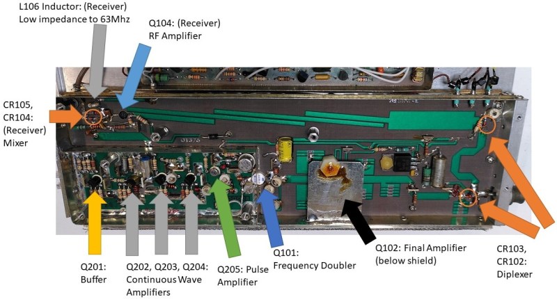
Inside the device, [Yeo Kheng Meng] found several densely packed boards, each isolated to minimize interference. The main PCB plays host to the Mostek MK3870 microcontroller, an 8-bit chip that screams along at 4 MHz and offers a spacious 128 bytes of RAM. It doesn’t sound like much to the modern AVR wrangler, but for 1977, it was cutting edge stuff.

Digging further, [Yeo Kheng Meng] opens up the metal cans that hold the transmitter and receiver. Thanks to the excellent documentation available for the device, which contains extensive schematics and block diagrams, he was able to ascertain the function of many of the components. Even if you’re unlikely to ever go hands on with this type of technology, it’s fascinating to see the thought and attention to detail that goes into even seemingly mundane aspects of the hardware.

Hungry for more airworthy engineering? We’ve taken a close look at some hardware pulled from a civilian airliner, as well as some battle-hardened electronics that once graced the cockpit of an AH-64 Apache attack helicopter.

Tricking A Vintage Clock Chip Into Working On 50-Hz Power

Thanks to microcontrollers, RTC modules, and a plethora of cheap and interesting display options, digital clock projects have become pretty easy. Choose to base a clock build around a chip sporting a date code from the late 70s, though, and your build is bound to be more than run-of-the-mill.

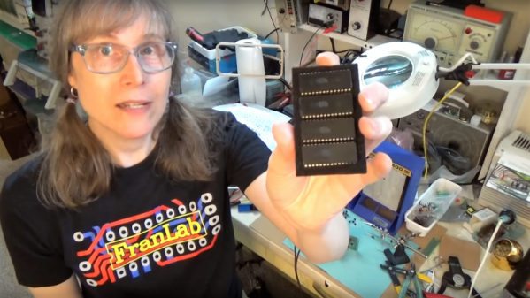
This is the boat that [Fran Blanche] finds herself in with one of her ongoing projects. The chip in question is a Mostek MK50250 digital alarm clock chip, and her first hurdle was find a way to run the clock on 50 Hertz with North American 60-Hertz power. The reason for this is a lesson in the compromises engineers sometimes have to make during the design process, and how that sometimes leads to false assumptions. It seems that the Mostek designers assumed that a 24-hour display would only ever be needed in locales where the line frequency is 50 Hz. [Fran], however, wants military time at 60 Hz, so she came up with a circuit to fool the chip. It uses a 4017 decade counter to divide the 60-Hz signal by 10, and uses the 6-Hz output to turn on a transistor that pulls the 60-Hz output low for one pulse. The result is one dropped pulse out of every six, which gives the Mostek the 50-Hz signal it needs. Sure, the pulse chain is asymmetric, but the chip won’t care, and [Fran] gets the clock she wants. Pretty clever.

[Fran] has been teasing this clock build for a while, and we’re keen to see what it looks like. We hope she’ll be using these outsized not-quite-a-light-pipe LED displays or something similar.

Continue reading “Tricking A Vintage Clock Chip Into Working On 50-Hz Power”