Sometimes, as hackers and makers, we can end up with messy lashed-together gear that is neither reliable nor tidy. Rackmounting your stuff can be a great way to improve the robustness and liveability of your setup. If you find this appealing, you might like CageMaker by [WebMaka].
This parametric OpenSCAD script can generate mounts for all kinds of stuff. Maybe you have a little network switch that’s just a tangle of wires on your desk, or a few pieces of audio gear that are loosely stacked on top of each other and looking rather unkempt. It would be trivial with this tool to create some 3D printed adapters to get all that stuff laced up nice and neat in a rack instead.
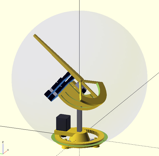
What hardware hacker doesn’t have a soft spot for transparent cases? While they may have fallen out of mainstream favor, they have an undeniable appeal to anyone with an interest in electronic or mechanical devices. Which is why the Orbigator built by [wyojustin] stands out among similar desktop orbital trackers we’ve seen.
Conceptually, it’s very similar to the International Space Station tracking lamp that [Will Dana] built in 2025. In fact, [wyojustin] cites it specifically as one of the inspirations for this project. But unlike that build, which saw a small model of the ISS moving across the surface of the globe, a transparent globe is rotated around the internal mechanism. This not only looks gorgeous, but solves a key problem in [Will]’s design — that is, there’s no trailing servo wiring that needs to be kept track of.
For anyone who wants an Orbigator of their own, [wyojustin] has done a fantastic job of documenting the hardware and software aspects of the build, and all the relevant files are available in the project’s GitHub repository.
The 3D printable components have been created with OpenSCAD, the firmware responsible for calculating the current position of the ISS on the Raspberry Pi Pico 2 is written in MicroPython, and the PCB was designed in KiCad. Incidentally, we noticed that Hackaday alum [Anool Mahidharia] appears to have been lending a hand with the board design.
As much as we love these polished orbital trackers, we’ve seen far more approachable builds if you don’t need something so elaborate. If you’re more interested in keeping an eye out for planes and can get your hands on a pan-and-tilt security camera, it’s even easier.
We love and hate OpenSCAD. As programmers, we like describing objects we want to 3D print or otherwise model. As programmers, we hate all the strange things about OpenSCAD that make it not like a normal programming language. Maybe µCAD (or Microcad) is the answer. This new entry in the field lets you build things programmatically and is written in Rust.
In fact, the only way to get it right now is to build it from source using cargo. Assuming you already have Rust, that’s not hard. Simply enter: cargo install microcad. If you don’t already have Rust, well, then that’s a problem. However, we did try to build it, and despite having the native library libmanifold available, Rust couldn’t find it. You might have better luck.
I modified a printer a few years ago to handle multiple filaments, but I will admit it was more or less a stunt. It worked, but it felt like you had to draw mystic symbols on the floor of the lab and dance around the printer, chanting incantations for it to go right. But I recently broke down and bought a color printer. No, probably not the one you think, but one that is pretty similar to the other color machines out there.
Of course, it is easy to grab ready-made models in various colors. It is also easy enough to go into a slicer and “paint” colors, but that’s not always desirable. In particular, I like to design in OpenSCAD, and adding a manual intervention step into an otherwise automatic compile process is inconvenient.
The other approach is to create a separate STL file for each filament color you will print with. Obviously, if your printer can only print four colors, then you will have four or fewer STLs. You import them, assign each one a color, and then, if you like, you can save the whole project as a 3MF or other file that knows how to handle the colors. That process is quick and painless, so the question now becomes how to get OpenSCAD to put out multiple STLs, one for each color.
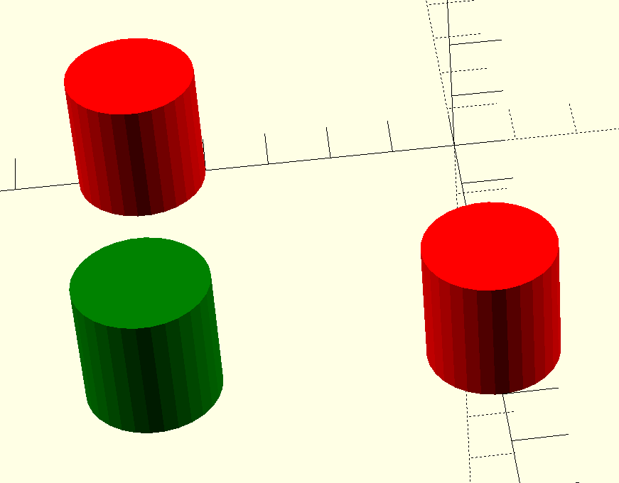
But… color()
OpenSCAD has a color function, but that just shows you colors on the screen, and doesn’t actually do anything to your printed models. You can fill your screen with color, but the STL file you export will be the same. OpenSCAD is also parametric, so it isn’t that hard to just generate several OpenSCAD files for each part of the assembly. But you do have to make sure everything is referenced to the same origin, which can be tricky.
OpenSCAD Development Version Test
It turns out, the development version of OpenSCAD has experimental support for exporting 3MF files, which would allow me to sidestep the four STLs entirely. However, to make it work, you not only have to run the development version, but you also have to enable lazy unions in the preferences. You might try it, but you might also want to wait until the feature is more stable.
Besides, even with the development version, at least as I tried it, every object in the design will still need its color set in the slicer. The OpenSCAD export makes them separate objects, but doesn’t seem to communicate their color in a way that the slicer expects it. If you have a large number of multi-color parts, that will be a problem. It appears that if you do go this way, you might consider only setting the color on the very top-most objects unless things change as the feature gets more robust.
A Better Way
What I really wanted to do is create one OpenSCAD file that shows the colors I am using on the screen. Then, when I’m ready to generate STL files, I should be able to just pick one color for each color I am using.
Many of us use touch pads daily on our laptops, but rarely do we give much thought about what they really do. In fact they are a PCB matrix of conductive pads, with a controller chip addressing it and sensing the area of contact. Such a complex and repetitive pattern can be annoying to create by hand in an EDA package, so [Timonsku] has written a script to take away the work.
It starts with an OpenSCAD script (originally written by Texas Instruments, and released as open source) that creates a diamond grid, which can be edited to the required dimensions and resolution. This is then exported as a DXF file, and the magic begins in a Python script. After adjustment of variables to suit, it finishes with an Eagle-compatible board file which should be importable into other EDA packages.
We’ve never made a touchpad ourselves, but having dome other such repetitive PCB tasks we feel the pain of anyone who has. Looking at this project we’re struck by the thought that its approach could be adapted for other uses, so it’s one to file away for later.
For those who love systems and structure, owning a 19-inch rack with just one slot filled is just not it. But what if the rest of your gear isn’t 19-inch? Well, then you go out and make it so, just like [Cal Bryant] did recently.
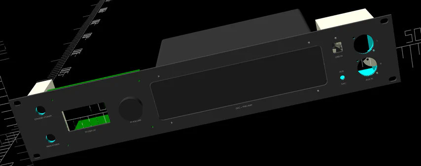
The goal was to consolidate multiple devices — DAC, input selector, streamer, and power routing — into a single 2U rackmount unit. His first attempts involved drilling 1U panels to attach gear with removable faceplates. That worked, but not all devices played nice. So his next step became a fully custom enclosure with CAD-modeled brackets and front panels.
OpenSCAD turned out to be a lifesaver, letting [Cal] design modular mounting solutions. Exporting proper circles for CNC turret punching however appeared to be a nightmare. It was FreeCAD to the rescue for post-processing. After some sanding and auto-shop painting, the final faceplate looked factory-made.
Custom switch boxes for power and audio routing keep things tidy, housing everything from USB to XLR inputs. A 4-pole switch even allows seamless swapping between his DAC and DJ controller, while UV-printed graphics bring the finishing touch to this project. For those looking to clean up their Hi-Fi setup (or just love modding for the sake of it), there’s a lot to learn from this build.
Not that it’s the kind of thing that pops into your head often, but if you ever do think of a cyanotype print, it probably doesn’t conjure up thoughts of modern technology. For good reason — the monochromatic technique was introduced in the 1840s, and was always something of a niche technology compared to more traditional photographic methods.
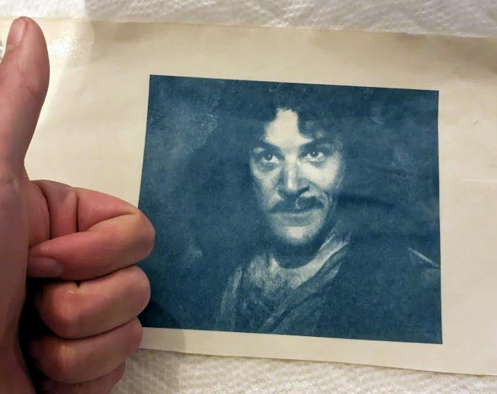
The original method is simple enough: put an object or negative between the sun and a UV-sensitive medium, and the exposed areas will turn blue and produce a print. This modernized concept created by [Gabe] works the same way, except both the sun and the negative have been replaced by a lightly modified resin 3D printer.
A good chunk of the effort here is in the software, as [Gabe] had to write some code that would take an image and turn it into something the printer would understand. His proof of concept was a clever bit of Python code that produced an OpenSCAD script, which ultimately converted each grayscale picture to a rectangular “pixel” of variable height. The resulting STL files could be run through the slicer to produce the necessary files to load into the printer. This was eventually replaced with a new Python script capable of converting images to native printer files through UVtools.
On the hardware side, all [Gabe] had to do was remove the vat that would usually hold the resin, and replace that with a wooden lid to both hold the UV-sensitized paper in place and protect the user’s eyes. [Gabe] says there’s still some room for improvement, but you wouldn’t know it by looking at some of the gorgeous prints he’s produced already.
No word yet on whether or not future versions of the project will support direct-to-potato imaging.