FPGA Calculator Uses Joystick

FPGAs are great fun, but sometimes you need a few starter projects under your belt. These projects might be something you could just as well do with a CPU, but you have to start somewhere. [LambdaPI] recently shared a 4-bit calculator created using an FPGA, and you can see it in the video below.

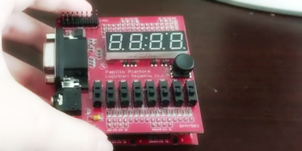
The calculator uses a Papilio FPGA board and a LogicStart accessory board for the display and switches. The Papilio normally uses schematic-based entry and Arduino code, but [LambdaPI] used VHDL. You enter the two 4-bit numbers on the 8 switches and then the joystick selects one of four operations (add, subtract, multiply, and divide).

Continue reading “FPGA Calculator Uses Joystick”

Papilio Duo: FPGA, Logic Analyzer, Debugger, And Arduino Compatible

Back

It’s been a while since we’ve seen some new boards that combine an FPGA and an Arduino, so naturally the state of the art is a little bit behind. The latest from [Jack Gassett], the Papilio Duo, aims to change that by addressing all the complaints of the original Papilio and adding some neat, modern features that you would expect on a board designed in 2014.

On board the Duo is an ATMega32u4, the same chip used in the Arduino Leonardo, allowing for easy integration with your standard Arduino projects. The top of the board is where the real money is. There’s a Spartan 6 FPGA with 9k logic cells, enough to run emulate some of the classic computers of yore, including the famous SID chip, Yamaha YM2149, and the Atari POKEY (!).  With host and device USB, 512k or 2M of SRAM, and an ADC on the FPGA inputs, this board should be able to handle just about everything you would want to throw at it. There’s even a breakout for HDMI on the bottom.

There are a few interesting software features of the Duo, including a full debugger for the ATMega chip, thanks to an emulated Atmel JTAG ICE MKII. Yes, an Arduino-compatible board finally has a real debugger. The FPGA can also implement a 32 channel logic analyzer, making this not only an extremely powerful dev board, but also a useful tool to keep around the workbench.

A Z80 Retro Microcomputer For The Papilio Pro FPGA Board

z80

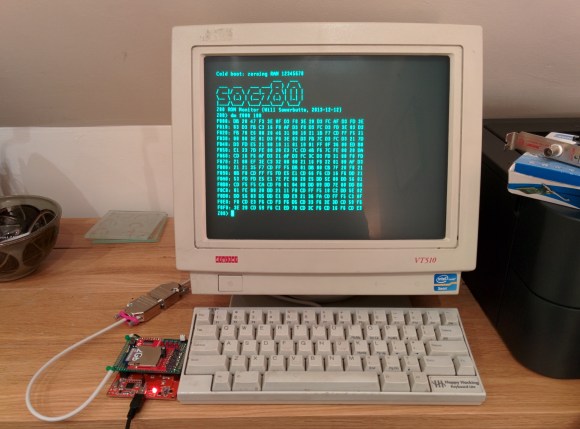
[Will] wrote a 128MHz Z80-based retro microcomputer which runs on a Papilio Pro board. For those who don’t know, the latter is built around a Spartan-6 LX9 FPGA so you may imagine that much work was required to implement all the computer features in VHDL. The T80 CPU core was taken from opencores, the SDRAM controller was imported from Mike Field’s work but [Will] implemented several additional functions on his own:

– a 4KB paged Memory Management Unit to translate the 16-bit (64KB) logical address space into a 26-bit (64MB) physical address space.

– a 16KB direct mapped cache to hide the SDRAM latency, using the FPGA internal block RAM

– a UART interface for external communications

He also ported CP/M-2.2, MP/M-II and UZI (a UNIX system) to the computer. His project is completely open-source and all the source code can be downloaded at the end of [Will]’s write up.

Thanks [hamster] for the tip.

A DiskVaccuum For Obsolete Disk Formats

drive

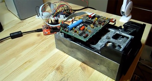
[Jim] has a box of disks for a very old Compucolor II computer, and with bit rot slowly setting in he figured it might be time to dump all those disks to a more permanent format. After reviewing the existing tools to read these disks, he decided to build his own floppy disk interface that he calls the DiskVaccuum.

The DiskVaccuum is based on a Papilio Pro FPGA board and a few chips worth of level conversion. The FPGA is able to read bits and move the head of the disk with ease, saving everything to the drive of a much more modern computer.

On the USB side of the Papilio board, [Jim] wrote a shell of sorts in Python to capture tracks on the disk, read out the track listing, save an image file, and do all the things a proper DOS should. Right now the project is only for the Compucolor II disk drive, but [Jim] played around with KiCAD enough to create a Papilio-to-disk-drive interface board with connectors for most of the disk drives of this particular vintage. The hope is to generalize the hardware and software to read disks for other systems, including those with 8-inch drives.

[Jim] put up a video describing the hardware and demoing his Python capture utility. You can check that out below.

Continue reading “A DiskVaccuum For Obsolete Disk Formats”

Breathing Life Into An Old LCD

panel

Out of the depths of a junk drawer, [Alex]’s friend pulled out an old monochrome LCD display. This is an older low-resolution display from ancient electronics that unfortunately doesn’t have its own controller chip. No worries, though, because with the help of an FPGA [Alex] figured out how to drive this display.

On the back of this display are eight Hitachi LCD drivers, six column shifters and two row shifters, allowing the LCD to display a 256×128 pixel image. Without an LCD controller, though, [Alex] couldn’t just send a static image to the LCD. Instead, he had to continuously refresh the display just like a VGA monitor.

With the help of a 1500-page PDF titled Hitachi LCD Controller/Driver LSI Data Book, [Alex] was able to dump pixels into the ICs on the display with the help of a Papilio One FPGA board. A lot of work just to display the beautiful [Lena], but she wouldn’t have it any other way.

Building A 100 MHz Frequency Counter

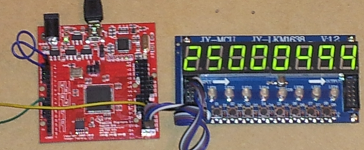
The great thing about building with gates is the crazy speeds you can achieve by using hardware directly (as opposed to working with simple microcontrollers). This 100 MHz frequency counter is a great example. [Michael] just finished building it using a Papilio board.

Of course we’re not talking about discreet chips here. The Papilio is an FPGA development board which means he is building with hardware gates, but that is still done by writing code. Above, the rig is measuring a 25 MHz being generated by a second FPGA board. Using the Papilio’s on board 32 MHz clock the device is capable of counting a frequency up to 100 MHz. You can see it measuring a 96.875  MHz signal in the video after the break. One interesting thing about that clip is that near the end he touches the crystal’s case with his finger and the Hertz really jump for a moment.

If the 8-digit display looks familiar that’s because [Michael] recently published a library to use it with an FPGA.

Continue reading “Building A 100 MHz Frequency Counter”

Laptop LCD Resurrection Gets Some Clean Packaging

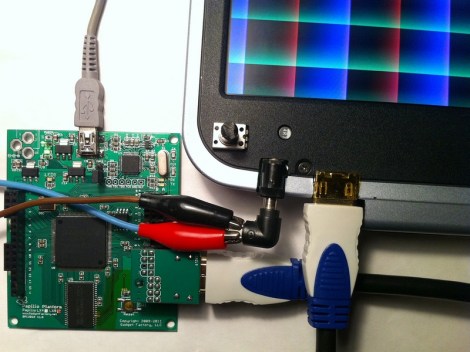
We love to see derivative works that take a great hack and make it even better. This LCD Laptop resurrection project is an excellent example. [Alex] took the work seen on this other FPGA LCD driver and delivered a leap forward on the final hardware packaging.

The link at the top drops you into the second page of [Alex’s] project thread. But if you go back to the beginning you’ll see the protoboard and spaghetti wiring which started off the process. Obviously if he plans to use this for a length of time it needs to be fortified or he’ll be cracking it open and grabbing a soldering iron again before long. But rather than just tidying up he ended up spinning his own circuit boards that make the screen look like it was manufactured to be used in this way.

He was able to mount the add-on board inside the LCD bezel, cutting out a space for the HDMI connector, barrel jack, trimpot, and the head of the inductor which was just a bit too large to fit inside. The trimpot allows him to adjust the LCD brightness. As far as we can tell the HDMI connector is just an easy way for him to deliver the drive signals from the Papilio board (FPGA) to the screen.