Pi Pico Throws Us For A (MIDI) Loop

Modern micro-controllers are absolute marvels, but it isn’t too many projects use one and nothing else. For an example of such simplicity, take a look at [oyama]’s Pi Pico MIDI looper.

It uses the PicoW to interface with a synth via MIDI-BLE, which can be anything from pro equipment to an app on your smartphone. The single control button is already provided by the Pico W– the bootsel button is wearing a lot of hats here, allowing one to select betwixt 4 tracks (all different drums), set the tempo, and input notes on the selected track.

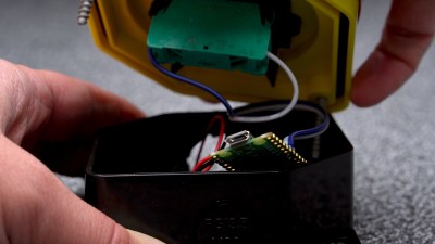
The action is simple: pound out the rhythm for each track, and it will repeat forever, or at least until you press the single button again to change it. There’s also a nice serial interface so you can see what’s going on via UART or USB. For what it does, it is amazingly simple: the BOM is one item, the Pi Pico W. To see it in action, check out the demo video below.

Given the ADC chops on the Pico, it would probably be easy to extend this build with a speaker to make a tiny stand-alone, one-button synth. Or you could add more buttons buttons, but then it’s no longer the beautifully simple single-line BOM project that [oyama] showed us.

Of course, everything is open-source on GitHub, under the BSD license, and forking is encouraged, so [oyama] would doubtless be more than happy to see you go nuts hacking and extending this tiny MIDI looper.

We’ve actually seen the MIDI-BLE standard used before, like this hack adding it to a Eurorack. If you like synths, you may be interested to see what it takes to design one from scratch, sans microcontroller. Continue reading “Pi Pico Throws Us For A (MIDI) Loop”

Simon Says With An RP2040

The team of [Michael] and [Chimdi] from Cornell’s Designing with Microcontrollers (ECE 4760) Fall 2023 session designed a version of Simon Says on an RP2040 which they call Pico Says. It uses UDP packets over WiFi to communicate between the players, and supports VGA graphics for output. Each player’s hardware consists of a Pico W module plus a control panel containing the four LEDs and buttons ( red, green, yellow, and blue ) plus send and reset buttons.

For purposes of this lab, the modules were build on a solderless breadboard and used perfboard for the control panels. They weren’t entirely happy with their choice of UDP because they experienced frequent datagram dropouts in the noisy environment of the microcontroller lab. They also planned to implement sound effects, but ran out of time after spending too much time on the WiFi implementation, and had to drop that feature. In the end, however, they wrapped up their project and demonstrated a working game. We can only speculate whether this bonus lesson in resource management was intended by [Dr. Hunter Adams] or not.

Two ECE 4760 course references are highlighted in the write-up that helped them jump-start the project: the UDP and VGA examples for the Pico. These are good links to put in your RP2020 toolbox for future projects, in addition to the ECE 4760 course home page itself. We’ve covered several of these projects recently, as well as the curriculum switch from the Microchip PIC32MX-based Microstick II to the RP2040 last Spring.

Continue reading “Simon Says With An RP2040”

A Bullet Time Video Booth You Can Build

[Sebastian Staacks] built a video booth for his wedding, and the setup was so popular with family, that it was only fitting to do one better and make some improvements to the setup, Matrix-style. The “bullet time” video effect was introduced by the classic movie franchise and makes for a splendid video transition effect for video montages.

Hardware-wise, the effect is pretty expensive, requiring many cameras at various angles to be simultaneously triggered, in order to capture the subject in a fixed pose with a rotating camera. Essentially you need as many cameras as frames in the sequence, so even at 24 frames per second (FPS), that’s a lot of hardware. [Sebastian] cheated a bit, and used a single front-facing camera for the bulk of the video recording, and twelve individual DSLRs covering approximately 90 degrees of rotation for the transition. More than that is likely impractical (not to mention rather expensive) for an automated setup used in as chaotic an environment as a wedding reception! So, the video effect is quite the same as in the movies, as this is a fixed pose, but it still looks pretty good.

A Pico-W hidden in there providing a BT connected interface button

[Sebastian] did consider going down the Raspberry Pi plus Pi-cam route, but once you add in a lens and the hassle of the casing and mounting hardware, not to mention availability and cost, snagging a pile of old DLSRs looks quite attractive. Connectivity to the camera is a simple 3.5 mm jack for the focus and trigger inputs, with frames read out via a USB connection.

For practical deployment, the camera batteries were replaced with battery eliminator adapters which step-up the 5 V from the USB connection to the 7.4 V the cameras need, but the current spike produced by the coordinated trigger of all twelve cameras overwhelmed any power supply available. The solution, to be practical, and not at all elegant, is to just have lots of power supplies hidden in a box. Sometimes you’ve just got a job to do.

Reproducing this at home might be a bit awkward unless you have exactly the same hardware to hand, but the principles are sound, and there are a few interesting details to dig into, if you were so inclined.

We’ve seen a few takes on the bullet-time effect over the years. We featured a Raspberry Pi-based hack, a couple of years back, and earlier still, someone even built a rig to take bullet-time videos of Tesla coil discharges, because why not?

Continue reading “A Bullet Time Video Booth You Can Build”