Swapping Nunchucks For A Steering Wheel

Rather than chasing pure performance and high quality graphics like other gaming companies, Nintendo has made a name for themselves over the last few decades by favoring not only artistic design and gameplay, but the physical design of the game systems. Of course the hybrid handheld Switch console is among these, but it also includes things like the novel design of the Nintendo 64 controller and, of course, the Wii nunchuck controllers. They’re not always met with resounding approval, though. Some of us tend to prefer more traditional gamepad design, and will go to extreme lengths to get it like this D-pad for playing Mario Kart Wii.

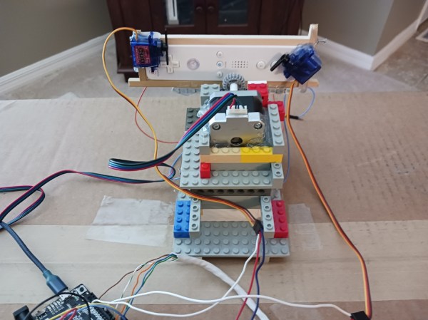
Rather than simply building a compatible controller for the Wii, or even using a GameCube controller, this controller setup takes a more roundabout approach. A Wiimote is placed in a holster built from Lego, and the game is set up to recognize it as if it were being used in its steering wheel mode. The Lego holster has a servo attached which can tilt the Wiimote from side to side, mimicking a player holding it to play the game, with another set of servos set up to press the various buttons. To control the controller, a homebrew D-pad built on perfboard with an Arduino at its core is used to send commands to the servos, allowing for a more standard controller layout to be used for the classic kart racing game than the steering wheel Wiimote allows.

While it’s quite obvious that there are simpler, easier solutions that avoid the sometimes awkward nature of using Wiimotes, we certainly appreciate the Rube Goldberg-like approach to setting up your gaming experience exactly the way you like. Whether that’s setting up an antique CRT effect for the authentic retro gaming experience or building a complete racing simulator from scratch, the gaming experience is ripe for personalization and unique builds like this one.

Continue reading “Swapping Nunchucks For A Steering Wheel”

How To Build Your Own 16-Bit System-on-Spreadsheet

Back in the hazy days of the  early home computers, many of us would rejoice at running our first BASIC applications, some of us even built our own 8-bit system from a handful of ICs and felt elated the moment the connected LEDs, screen or other output device would show signs of life. It is this kind of excitement that [Inkbox] has managed to bring to the bane of every office worker: spreadsheet programs like Excel. How, you may ask? Why, by implementing a completely functional 16-bit system with 16 general purpose registers, 128 kB of RAM and a 128×128 pixel color display, all inside an Excel spreadsheet, making it conceivably the world’s first System-on-Spreadsheet (SoS).

Perhaps the most tantalizing aspect of this approach is that it provides a very good visual way to indicate what is happening inside the system using color codes and clearly segregated and marked functional elements. Not only can it be programmed manually, but [Inkbox] also created an assembler for the CPU’s ISA – called Excel-ASM16 – all of which is available from the ExcelCPU GitHub project page. The ASM is assembled into a ROM.xlsx file that can then be run by the CPU.xlsx file by triggering the Read ROM button. After this you are confronted with the realization that although it all works, it’s also incredibly slow, at about 2-3 Hz.

Still, with all the elegance of an IMSAI 8080 front panel, we cannot help but give full points for this achievement. Plus it gives many of us something to do during those exceedingly dull meetings where only serious applications like office suites are allowed.

Continue reading “How To Build Your Own 16-Bit System-on-Spreadsheet”

A Basic USB-C Primer

Over the last five years or so there has been a quiet take-over of the ports on laptops, phones, and other devices, as a variety of older ports as well as the familiar USB A and micro USB sockets have been replaced by the now-ubiquitous USB-C port. It’s a connector which can do so many things, so many in fact that it bears a handy explanation. The Electromagnetic Field 2022 hacker camp has been quietly uploading videos of its talks, and a recent one has [Tyler Ward] explaining the intricacies of the interface.

Many of you will be familiar with XKCD number 927 which makes a joke about proliferating connector standards, and it’s evident that USB-C is a rare case of a connector which bucks the trend of simply making another standard, and has instead created something with which it makes sense to replace what went before. We learn about the intricacies of inter-device communications and USB-PD, and the multiple high-speed connection  lanes shoehorned into it. That one small connector can plug into a laptop and provide power, USB peripherals including network, and display, is nothing short of amazing. Take a look at the video below the break, and if you’re interested in diving deeper, have a look at our colleague [Arya Voronova]’s USB-C for hackers series.

Continue reading “A Basic USB-C Primer”

Design Secrets Of Fantastic, Hand-made Puzzle Boxes

[Kagen Sound] is a woodworker and artist who gives a great behind-the-scenes look at his amazingly high-quality puzzle boxes (video). Not only do his varied puzzle box designs show his math background, but they are all made entirely of wood. There are no nails or fasteners; just intricately-fitted wood and some glue.

There’s a lot of variety in his designs, and while it’s all fantastic from beginning to end, two things stood out to us as being of particular interest. One is the “Plus Box” which makes a clicking sound when the pieces are moved (at 2:47) thanks to a clever wooden spring. [Kagen] shows an example of the concept, where a flat wood piece with slots cut from the sides acts as a spring and clicks into notches when moved, providing audible and tactile feedback without anything other than wood.

The other is a patterned puzzle box (at 7:10) whose geometric designs change as the user moves the pieces. A reminder that [Kagen]’s devices are made entirely of wood and glue, so the design comes from two different types of wood assembled and cut at an angle to create the patterns seen. [Kagen] shaves thin layers of veneer from this block to attach to the puzzle pieces as needed to create the patterns without resorting to ink, paint, or decals.

[Kagen] has a math degree but is entirely self-taught as a woodworker, so don’t let lack of formal training stop you from experimenting. You can watch him give a tour of his work in the video, embedded below.

Feeling the urge to make your own puzzle boxes? Take a look at some we’ve seen over the years, and we even have a collection of single-line cryptex fonts to make laser-engraving puzzle bits a little easier.

Continue reading “Design Secrets Of Fantastic, Hand-made Puzzle Boxes”

Simon Says With An RP2040

The team of [Michael] and [Chimdi] from Cornell’s Designing with Microcontrollers (ECE 4760) Fall 2023 session designed a version of Simon Says on an RP2040 which they call Pico Says. It uses UDP packets over WiFi to communicate between the players, and supports VGA graphics for output. Each player’s hardware consists of a Pico W module plus a control panel containing the four LEDs and buttons ( red, green, yellow, and blue ) plus send and reset buttons.

For purposes of this lab, the modules were build on a solderless breadboard and used perfboard for the control panels. They weren’t entirely happy with their choice of UDP because they experienced frequent datagram dropouts in the noisy environment of the microcontroller lab. They also planned to implement sound effects, but ran out of time after spending too much time on the WiFi implementation, and had to drop that feature. In the end, however, they wrapped up their project and demonstrated a working game. We can only speculate whether this bonus lesson in resource management was intended by [Dr. Hunter Adams] or not.

Two ECE 4760 course references are highlighted in the write-up that helped them jump-start the project: the UDP and VGA examples for the Pico. These are good links to put in your RP2020 toolbox for future projects, in addition to the ECE 4760 course home page itself. We’ve covered several of these projects recently, as well as the curriculum switch from the Microchip PIC32MX-based Microstick II to the RP2040 last Spring.

Continue reading “Simon Says With An RP2040”

Human-Interfacing Devices: The Descriptor Heist

Today, we’ll build our own input devices. And they will be easy to create and write firmware for, they will work perfectly, and they will be cross-platform. We can do that with help of the Human Interface Device (HID) standard, and by way of introduction, so that you never get confused by what a “descriptor” means, and we’ll build our own HID device — a Human Interface Device device. The way we build them won’t require reading specifications – instead, I’ll teach your how to steal HID descriptors from existing devices, tweak them for our purposes, and use them in our devices to harness the power of HID.

For decades now, it’s been possible to build a HID mouse or keyboard by using a library or two, and it’s been a godsend for hackers all around the world. However, these libraries are typically confined to a certain template and inflexible, and we hackers often go outside of what’s expected. HID allows for much more than a simple keyboard or a mouse. That’s why today we’re building a touchscreen – something not yet covered online or by libraries.

HID lets you build devices that are friendly. They don’t need drivers, they are plug and play, and they do what you expect them to do. At its core, the HID standard is as simple as is ubiquitous. You can tunnel HID over USB, Bluetooth, I2C, and modern-day operating systems support all three of these. Today, let’s go through the basics of HID, and then build a USB touchscreen out of a SPI-connected resistive touchscreen, with help of the usual RP2040+MicroPython combo. I will also give you a toolkit for how to debug a Human Interface Device device as thoroughly as possible – specifically on Linux, showing all the HID debug and introspection capabilities that Linux gives you. But it’ll work on Windows too through the beauty of standardization.

Continue reading “Human-Interfacing Devices: The Descriptor Heist”

The World’s First Microprocessor: F-14 Central Air Data Computer

When the Grumman F-14 Tomcat first flew in 1970, it was a marvel. With its variable-sweep wing, twin tail, and sleek lines, it quickly became one of the most iconic jet fighters of the era — and that was before a little movie called Top Gun hit theaters.

A recent video by [Alexander the ok] details something that was far less well-documented about the plane, namely its avionics. The Tomcat was the first aircraft to use a microprocessor-driven flight system, as well as the first microprocessor unit (MPU) ever demonstrated, beating the Intel 4004 by a year. In 1971, one of the designers of the F-14’s Central Air Data Computer (CADC) – [Ray Holt] – wrote an article for Computer Design magazine that was naturally immediately classified by the Navy until released to the public in 1998.

The MPU in the CADC is called the Garrett AiResearch MP944, and consists of a number of ICs that together form a full computer. These were combined in the CADC with additional electronics to control many elements of the airplane automatically, including the weapons system and the variable-sweep wing configuration. This was considered to be essential based on experiences with the F-111 and its very complex electromechanical flight computer, which was an evolution of the 1950s-era Bendix CADC.

The video goes through the differences between the 4-bit Intel 4004 and the 20-bit MP944, questioning whether the 4004 is even really an MPU, the capabilities of the MP944 and its system architecture. Ultimately the question of ‘first’ and that of ‘what is an MPU’ will always be somewhat fuzzy depending on your definitions, but there is no denying that the MP944 was a marvel of large-scale integration.

Continue reading “The World’s First Microprocessor: F-14 Central Air Data Computer”