Everyone needs a bench power supply, and rolling your own has almost become a rite of passage for hackers. For a long time, the platform of choice for such builds seemed to be the ATX power supply from a computer. While we certainly still see those builds, a lot of the action has switched to those cheap eBay programmable DC-DC converters, with their particolored digital displays.
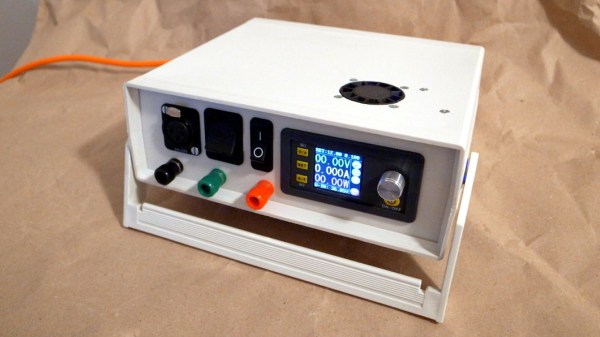
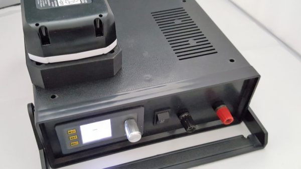
This hybrid bench and portable power supply is a good example of what can be accomplished with these modules, and looks like it might turn out to be a handy tool. [Luke] centered his build around the DPS3003, a constant current and constant voltage buck converter that can take up to 40-VDC input and outputs up to 32 volts at 3 amps. In bench mode, the programmable module is fed from a mains-powered 24-volt switching supply. For portable work, an 18-volt battery from a Makita drill slips into a 3D-printed adapter on the top of the case. The printed part contains a commercial terminal [Luke] scored on eBay, but we’d bet the entire thing could be 3D printed. And no problem if you change power tool brands — just print another adapter.
Those little eBay power supply modules have proven to be an enabling technology, at least judging by the number of clever ways we’ve seen them used lately. From this combination bench PSU and soldering iron supply to a portable PSU perched atop a battery, these things are everywhere. Heck, you can even reflash the firmware and make them do your bidding.
[via Dangerous Prototypes]