There’s an interesting side effect of creating a popular piece of science fiction: if you wait long enough, say 30 or 40 years, there’s a good chance that somebody will manage to knock that pesky “fiction” bit off the end. That’s how we got flip phones that looked like the communicators from Star Trek, and rockets that come in for a landing on a tail of flame. Admittedly it’s a trick that doesn’t always work, but we’re not in the business of betting against sufficiently obsessed nerds either.
 Coming in right on schedule 32 years after the release of Metroid on the Nintendo Entertainment System, we now have a functional laser arm cannon as used by the game’s protagonist Samus Aran, courtesy of [Hyper_Ion]. It’s not quite as capable as its video game counterpart, but if your particular corner of the solar system is under assault from black balloons you should be in good shape. Incidentally no word yet on a DIY Power Suit that folds the wearer up into a tiny ball, but no rush on that one.
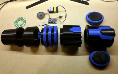
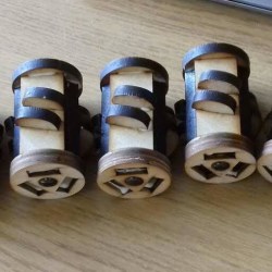
Modeled after the version of the weapon Samus carried in 2002’s iconic Metroid Prime, [Hyper_Ion] 3D printed the cannon in a number of pieces that screw together in order to achieve the impressive final dimensions. He printed it at 0.3 mm layers to speed up the process, but as you can probably imagine, printing life-size designs like this is not for the faint of heart or short of time. While the use of printed threads does make the design a bit more complex, the fact that the cannon isn’t glued together and can be broken down for maintenance or storage is a huge advantage.
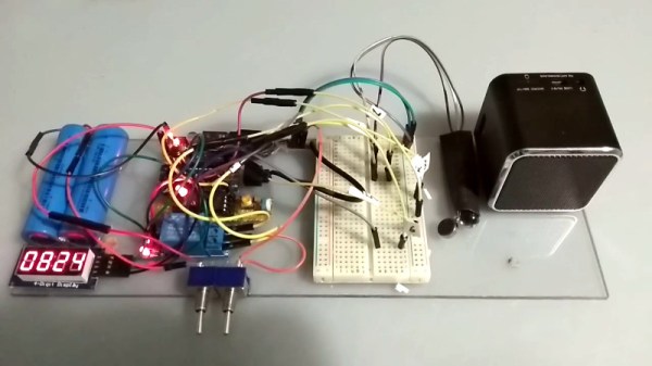
Ever popular NeoPixel strips give the cannon a bit of flash, and a speaker driven by a 2N2222 transistor on an Arduino Nano’s digital pin allows for some rudimentary sound effects with nothing more than a PWM signal. In the video after the break you can see how the lights and sounds serve as a warning system for the laser itself, as the cannon can be seen “charging up” for a few seconds before emitting a beam.
Of course, this is the part of the project that might have some readers recoiling in horror. To provide some real-world punch, [Hyper_Ion] has equipped his arm cannon with a 2.5W 450nm laser module intended for desktop engraving machines. To say this thing is dangerous is probably an understatement, so we wouldn’t blame you if you decided to leave the laser module off your own version. But it certainly looks cool, and as long as you’ve got some proper eye protection there’s (probably) more dangerous things you can do in the privacy of your own home.
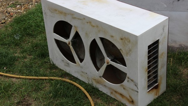
Shame this kind of technology wasn’t really practical back when [Ryan Fitzpatrick] made this fantastic Power Suit helmet for a Metroid fan production.
Continue reading “Laser Arm Cannon Scares More Than Metroids” →
 The iconic robot helmets of Daft Punk feature prominently as challenging DIY hardware projects in their own right, and the results never disappoint. But [Nathaniel Stepp]’s
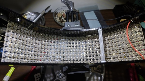
 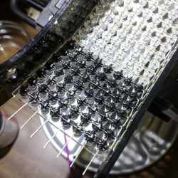 After the whole array was assembled and working, the back of each LED appears to have then been carefully coated in what looks like Plasti-Dip in order to block light, probably to minimize the blinding of the wearer. A small amount of space between each LED allows the eyeballs inside the helmet to see past the light show in the visor.