You’re working away busily at your project. A pcb here cabled to a breadboard in the middle, and over there some motors and other devices. It should work but it doesn’t. Time to hook-up the multimeter but the test point is on the other side. As things are moved around to reach the point, the magic smoke escapes from a critical component. Should have put those pliers away.


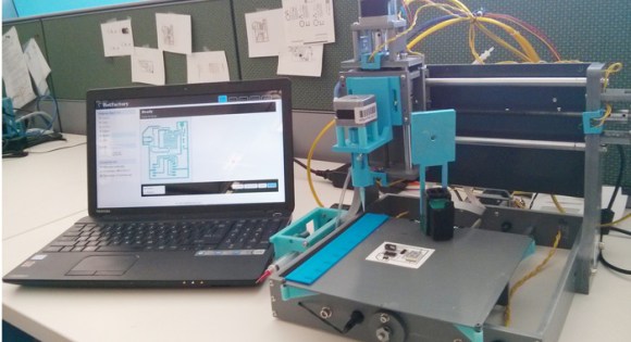
Workbenches are always messy. [Ryan Clark] may have an idea that can help. His Jigmod system — currently running a kickstarter campaign — uses an acrylic a polycarbonate sheet with a grid of mounting holes to keep prototyping hardware in place. If you need to move the prototype around there is no strain on the wiring and no way to set a circuit down on that pair of pliers. The positioning of everything is your decision.
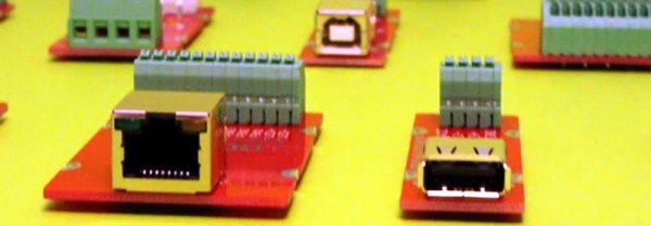
[Ryan] is also providing breakout type boards for connectors like USB and Ethernet, switches, battery holders, and other typical components. This is one place where the system really shines. A lot of these interface connectors tend to be breadboard-unfriendly and the terminal blocks these modules offer solves those issues. When you need to demonstrate your project it’s easy to transport since everything is attached to the plate. No more disconnecting cables, especially jumper wires, and hoping you get them all hooked back the right way at the destination.
With so many dev boards out there we really enjoy seeing jigs that can hold them along with a breadboard. This Stickvise-inspired 3D printed jig sticks out in our minds as a favorite. Do you have your own system of organizing your prototype builds? We’d love to hear about it in the comments!
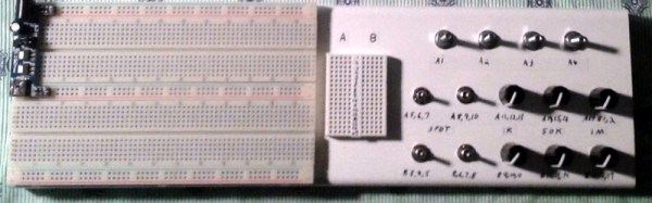
 Of course, it is easy enough to just connect breadboard wires to component, but [Chuck] went further than that. Using boxes of different types (including a cigar box), he mounted the components properly and also wired them to a breadboard for easy connection.