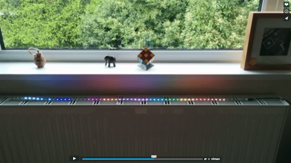
Massive Microsoft Machinations For Makers

If you’re not stuck in the tech news filter bubble, you may not have heard the Microsoft Build Developers Conference is going on right now. Among the topics covered in the keynotes are a new Office API and a goal to have Windows 10 running on a Billion devices in a few years.

There are, however, some interesting things coming out of the Build conference. Windows 10 is designed for hackers, with everything from virtual Arduino shields running on phones, Windows 10 running on Raspberry Pis, and Visual Code Studio running on OS X and Linux.

This is not the first time in recent memory Microsoft has courted the maker market. Microsoft begrudgingly supported the hardware dev scene with the PC version of the Microsoft Kinect, and a year or two ago, Microsoft rolled out drivers for 3D printers that were much more capable than the usual serial interface (read: the ability for printer manufacturers to add DRM). To the true, tie-die wearing, rollerblade-skating, acoustic coupler-sporting, Superman III-watching hackers out there, these efforts appear laughable – the product of managers completely out of touch with their audience.

Depending on your perspective, the new releases for the Arduino, Raspberry Pi, and other ‘maker-themed’ hardware could go one way or the other.

As far as educational efforts go, the Windows Remote Arduino and Windows Virtual Shields for Arduino are especially interesting. Instead of filling a computer lab up with dozens of Arduinos and the related shields, the WVSA uses the sensors on a Windows 10 smartphone with an Arduino. Windows Remote Arduino allows makers to control an Arduino not through the standard USB port, but a Bluetooth module.

If Arduinos aren’t your thing, the Windows 10 IoT preview for the Raspberry Pi 2 and Minnowboard Max is out now. The Win10 IoT distribution does not yet have working WiFi or Bluetooth, making it the single most useless operating system for Internet of Things devices. It was, however, released at the Build conference.

Also announced was a partnership with a fabulous hardware project hosting site, Hackster.io. Microsoft and Hackster.io will be collaborating with hackathons and other events focused on Windows technology. I get why they wouldn’t want another, vastly more popular project hosting site doing this, but I’m a little confused at why Instructables wasn’t the top Microsoft pick.

As always, you may express your infinite derision in the comments below. Spelling Microsoft with a dollar sign will result in a ban.

DOTS Uses Paint To Control Raspberry Pi 2

Two tables down from us at SXSW Create the Raspberry Pi foundation had a steady stream of kids playing Minecraft on Raspberry Pi, and picking up paint brushes. The painting activity was driven by a board they spun for the event that used conductive paint to control the Raspberry Pi 2.

rear-of-the-raspberry-pi-2The board uses the HAT form factor which it a fancy name for a shield (also a clever one as it stands for “Hardware Attached on Top”). You can see the back side of the board in this image. It utilizes an extremely low-profile surface mount pin socket.

The front side exposes several circular pads of copper which build up a “connect-the-dots” game that is played by painting conductive ink on the surface. This results in an airplane being pained on the board, as well as displayed on the computer. There is a set of pads that allow the user to select what color is painted on the monitor.

We like this as a different approach to education. Kids are more than used to tapping on a touchscreen, clicking a mouse, or pounding a keyboard. But conductive ink provides several learning opportunities; the paint simply connects the inner circle with the outer circle; one of these circles is the same on every single dot (ground); anything that connects these two parts of the dot together will result in input for the computer. Great stuff!

The foundation is taking the boards to Maker Faire Bay Area next month so stop by to see these in action. You can read about the production process for the DOTS board on the Raspberry Pi website. They’re giving away a few boards to software developers who want contribute to the project. And our video interview with [Matt Richardson] is found after the break.

Continue reading “DOTS Uses Paint To Control Raspberry Pi 2”

Header of the Project Byzantium website

Meshing Pis With Project Byzantium

If internet service providers go down, how are we going to get our devices to communicate? Project Byzantium aims to create an “ad-hoc wireless mesh networking for the zombie apocalypse.” It’s a live Linux distribution that makes it easy to join a secure mesh network.

[B1tsh1fter] has put together a set of hardware for running Byzantium on Pis in emergency situations. A Raspberry Pi 2 acts as a mesh node, using a powerful USB WiFi adapter for networking. Options are provided for backup power, including a solar charger and a supercapacitor based solution.

The Pi runs a standard Raspbian install, but uses packages from the ByzPi repository. This provides a single script that gets a Byzantium node up and running on the Pi. In the background, OLSR is used to route packets through the mesh network, so that nodes can communicate without relying on a single link.

The project has a ways to go, but the Raspberry Pi based setup makes it cheap and easy to get a wide area network up and running without relying on a single authority.

The Raspberry Pi Action Camera

Action cameras like the GoPro, and the Sony Action Cam are invaluable tools for cyclists and anyone else venturing into the great outdoors. These cameras are not really modifiable or usable in any way except for what they were designed for. [Connor] wanted a cheaper, open-source action camera and decided to build one with the Raspberry Pi.

[Connor]’s Pi action cam is built around the Raspberry Pi Model A+ and the Pi camera. This isn’t a complete solution, so [Connor] added a bluetooth module, a 2000 mAh battery, and a LiPo charger.

To keep the Pi Action Cam out of the elements, [Connor] printed an enclosure. It took a few tries, but eventually he was able to mount everything inside a small plastic box with buttons to start and stop recording, a power switch, and a USB micro jack for charging the battery. The software is a script by [Alex Eames], and the few changes necessary to make this script work with the hardware are also documented.

This was the most intensive 3D printing project [Connor] has ever come up with, and judging by the number of prints that don’t work quite right, he put a lot of work into it. Right now, the Pi action cam works, but there’s still a lot of work to turn this little plastic box into a completed project.

Mapillary For The Raspberry Pi

If you live out in the boondocks, out of reach from the Google Maps car, you might have noticed there aren’t too many pictures of your area on the Internet. Mapillary is hoping to change that with crowdsourced photos of the entire planet, with mobile apps that snap a pic and upload it to the web. [sabas1080] is bringing this capability to the most popular ARM dev board out there, the Raspberry Pi.

The Raspberry Pi is not a phone, the usual way to upload pics to Mapillary. There’s no GPS, so geotagging is out of the question. The Pi doesn’t have a camera or a screen, and if you’re taking pictures of remote locations, a battery would be a good idea.

All these pieces are available for the Pi, though; [sabas1080] sourced a display from Adafruit, the camera is a standard Raspi affair, and the GPS is a GY-NEO6MV2 module from the one of the numerous Chinese retailers. Add a big power bank battery, and all the hardware is there.

The software is where this build gets tricky. Mapillary has a nice set of free tools written in Python, no less, but this is only part of the build. [sabas1080] needed to connect the camera, set up the display, and figure out how to make everything work with the Mapillary tools. In the end, [sabas] was able to get the entire setup working as a programmable, mobile photo booth.

Switch Mains Power With An ESP8266

Before we begin, we must begin with an obligatory disclaimer: handling mains voltage can be very dangerous. Do not do so unless you are qualified! You could burn your house down. (Without the lemons.) That being said, [TJ] has created an interesting dev board for controlling mains voltage over WiFi with the now-ubiquitous ESP8266 module. At only 50mm x 25mm, it is easily small enough to fit inside a junction box!

Called the MPSMv2, the core of the project is the ESP8266 module. The dev board itself can support anything with GPIO pins, whether it’s an Arudino, Raspberry Pi, or anything else with those features. Flashing the NodeMCU firmware is pretty much all that needs to be done in order to get the device up and running, and once you get the device connected to your WiFi you’ll be able to control whatever appliances you want.

The device uses a triac to do the switching, and is optically isolated from mains. Be sure to check out the video after the break to see the device in action. All in all, this could be a great way to get started with home automation, or maybe just do something simple like build a timer for your floor lamp. Anything is possible!

Continue reading “Switch Mains Power With An ESP8266”

Raspberry Pi Controlled Chicken Door

We’re not sure if the Chickens know it yet, but they could be one of the reasons for all this IoT craze now a days. Look for chicken coop, and out come dozens of posts from the Hackaday chest.

Here’s another one from self confessed lazy engineer [Eric]. He didn’t want to wake up early to let his chickens out in the morning, or walk out to the coop to lock them up for the night to protect them from predators like Foxes, Raccoons and Opossum. So he built a Raspberry-Pi controlled chicken coop door that automates locking and unlocking. The details are clear from his video which you can watch after the break. The door mechanism looks inspired from an earlier anti-Raccoon gravity assist door.

The hardware (jpg image) is simple – a couple of hall sensors that detect the open/close status of the coop door that is driven by a DC motor via a bridge controller. The whole setup is controlled using a Raspberry-Pi and this is where the fun starts – because he can now add in all kinds of “feature creep”. Motion sensor, camera, light array, and anti-predator gizmos are all on his drawing board at the moment. Add in your feature requests in the comments below and let’s see if [Eric] can build the most advanced, complicated, gizmo filled chicken coop in the Universe. Combine that with this design, and it could even turn out to be the most beautiful too.

Continue reading “Raspberry Pi Controlled Chicken Door”