The Hackaday tips line is always full of the coolest completed projects, but only rarely do we see people reaching out for help on their latest build. We’ll help when we can, but [Tim]’s relay-based CPU has us stumped.
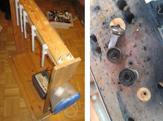
[Tim] already has the design of his relay CPU completed with a 12-bit program counter, sequencer, ALU, and a transistor-based ROM. The problem he’s having deals with the mechanics and layout of his homebuilt CPU. Right now, all the relays (PC pin, we guess) are glued top-down to a piece of cardboard. This allows him to easily solder the wires up and change out the inevitable mistakes. This comes with a drawback, though: he’s dealing with a lot of ‘cable salad’ and it’s not exactly the prettiest project ever.
The ideal solution, [Tim] says, would be a PCB with through-hole plating, but this isn’t easy or cheap for the home fab lab. We’d suggest some sort of wire wrap setup, but proper wire wrap sockets and protoboards are for some reason unreasonably expensive.
If you have an idea on how to do the mechanical layout and connections of a relay-based computer, drop a note in the comments. [Tim] has a very cool project here, and it would be a shame if he were to give up on it due to a lack of tools.
Video below, and if you’re having a problem with a project, feel free to send it in.
 [David Burroughs] wrote in to share