Bit Banging Through A USB Parallel Port Adapter

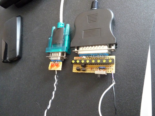
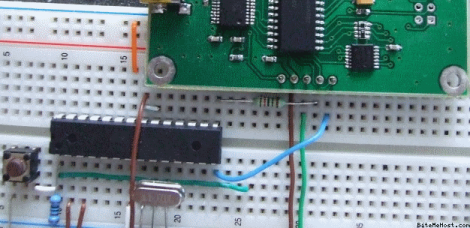
If you’ve ever looked into low-level parallel port access you may have learned that it only works with actual parallel port hardware, and not with USB parallel port adapters. But here’s a solution that will change your thinking. It borrows from the way printers communicate to allow USB to parallel port bit banging without a microcontroller (dead link, try Internet Archive).

Sure, adding a microcontroller would make this dead simple. All you need to do is program the chip to emulate the printer’s end of the communications scheme. But that’s not the approach taken here. Instead the USB to RS232 (serial) converter also pictured above is used as a reset signal. The strobe pin on the parallel port drives an inverter which triggers a thyristor connected to the busy pin. Thyristors are bistable switches so this solution alone will never clear the busy pin. That’s where the serial connection comes into play. By alternating the data transmitted from the computer between the bit-bang values sent to LP0 and 0xF0 sent to the serial connector the eight parallel data bits become fully addressable. See the project in action in the clip after the break.

IR Remote As PC Input

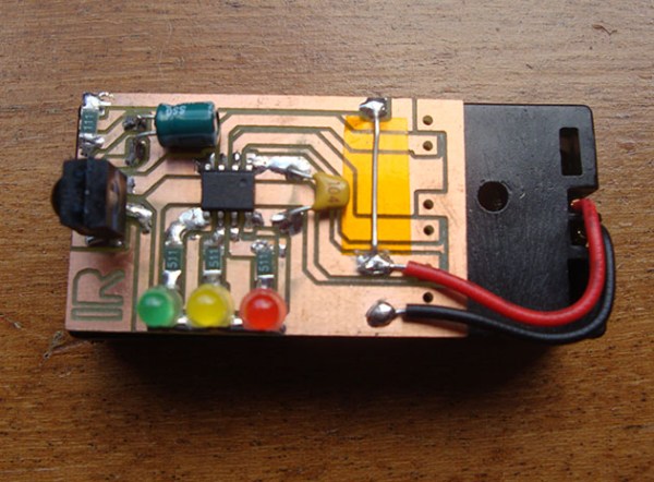
As a learning experience [GeriBoss] put together an IR remote control receiver board for his PC. His want of volume control from across the room was reason enough to undertake the project, and he got to work with a 38 kHz receiver module and Manchester encoding in the process.

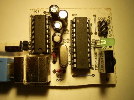
The decoder portion of the project is built around an ATtiny2313 chip. The external interrupt pin (INT0) is connected to a TSOP31238. When it decodes a valid remote code it pushes a character to the RS232 chip connecting to the computer’s serial port.

We think this is a wonderful accomplishment for [GeriBoss], but we encourage him to refine the design further. You’ll notice in the image there’s a USB port on the board which is only used to provide regulated power. We know it’s possible to use V-USB with the ATtiny2313 to add USB functionality and this would be a great way to learn about it. We’d also like to mention the resistor and capacitor suggested for filtering the IR receiver module signal. We’ve included the recommended application schematic for that part after the break.

Continue reading “IR Remote As PC Input”

GPIB Connectivity Twofer

Dust off that old GPIB hardware and hook it up to your modern computing platform using either of these two solutions. If you haven’t a clue what we’re talking about you probably don’t own any fifty-year-old test equipment. But the General Purpose Interface Bus (aka IEEE-488) was fairly common on 1960’s era test equipment like multimeters and logic analyzers.

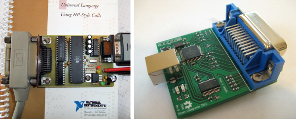
[Sven Pauli] is responsible for the RS232 GPIB interface board (translated) in the upper left. It uses an ATmega16 and a couple of classic bus driver chips to get the job done.

To the lower right is a USB to GPIB converter board that [Steven Casagrande] developed. This one is PIC based, using the 18F4520 and an FTDI chip to handle the USB side of the equation.

Check out the connector that is used for this protocol. We’d bet that’s not the easiest part to source. But at least now you’ll know what you’re looking at when pawing through the flea market offerings.

Using An ATmega8 To Program PIC24FJ Chips

[Fezoj] likes to play around with microcontrollers and decided that he wanted to try a Bus Pirate as a new tool in his adventures. Since it’s open hardware he had his own board made and populated it himself. The trouble is, he works only with AVR chips and doesn’t have a PIC programmer. No problem, he figured out how to flash the PIC24FJ using an ATmega8.

To get started, he grabbed a copy of the flash programming specifications from Microchip. Once he had implemented the protocol in the AVR code, it was just a matter of getting the downloaded PIC firmware to the AVR. An RS232 chip gives him the serial connection he needs, with the help of his own programming software written with Visual Studio.

It’s not a robust solution for prototyping on the PIC platform, but maybe it could be developed for that purpose. For now, all he needed was a bootloader so that he could flash the Bus Pirate via a USB connection.

[via Dangerous Prototypes]

Arduino Weather-station To Internet Bridge

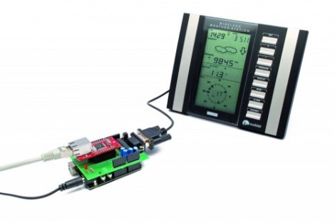
Here’s a project that looks to eliminate the PC necessary for pushing weather station data to the Internet. When you think about it, getting data from your own weather sensing hardware to a site like Weather Underground doesn’t require very much processing at all. The largest chunk of the puzzle is a window to the Internet, and that can be easily accomplished with a microcontroller rather than an always-on computer.

In this case, [Boris Landoni] is using an Arduino along with an RS232 shield and an Ethernet shield. The weather station, a La Crosse WS23xx series, already has an RS232 serial port for grabbing the data. The shield is necessary to step the voltage down to levels that will play nicely with Arduino. It also gives you a D-Sub connector for easy hook up. From there he hit up the documentation for Weather Undeground API, writing code to build the necessary string which is pushed over the Ethernet connection at regular intervals.

If your weather station only offers a USB port you’re not out of luck. Using an embedded platform with USB host functionality you can achieve the same results as we see here.

Adding RS232 To A Multimeter The Hard Way

You might want to store information from a multimeter to be graphed over time. This comes with pretty much all of the high-end professional models. But if you buy a super cheap meter you can bet this isn’t an option. [Jazzzzzz] has found a way to pull the data from a $4 meter via RS232. It’s not impossible, but we definitely think he’s doing it the hard way. That’s because he’s not just tapping into a dormant feature. He’s actually adding a microcontroller to sample the data and push it via the RS232 protocol.

On the bright side, this is easier than building a multimeter from scratch. The sampling circuits are still being used, with a PIC 16F688 intercepting the signals as they enter the stock microcontroller. The signal he was after comes into the chip on just one pin, but to get the readings right on the PIC he had to use an OpAmp. That’s only part of the puzzle as he also needed a way to tell what the selector switch was set at. In the end, adding a potentiometer and reading its value let him calculate the position.

[Thanks Karl]

Making Oscilloscopes From ARM Development Boards

If you’ve got an ARM development board gathering dust in the corner of your shop, perhaps you could repurpose it as an oscilloscope. [Arend-Paul Spijkerman] was able to use an mbed and LPCXpresso as the hardware end of an oscilloscope. He didn’t use a standalone screen as a display, instead opting to push the scope readings from the hardware to a computer for display. This was greatly simplified by using StampDock as a basis for the GUI.

His circuit diagrams calls for an RS-232 connection for the LPCXpresso but not for the mbed. We’re not quite familiar enough with the mbed to know why, but perhaps those in the know can clue us in by leaving a comment. The probe connections are quite simple, each made up of a voltage divider and a pair of diodes. But the breadboard above looks much busier because it has two oscilloscope circuits built on it, and there’s a 10 MHz clock and a 4040 ripple counter which were used to provide a test signal.