Globe-Shaped World Clock Is A 3D-Printed Mechanical Marvel

Time zones are a complicated but necessary evil. Humans like the numbers on the clock to vaguely match up with what the sun is doing in the sky outside. To that end, different places in the world keep different time. If you want to keep track of them in a very pretty fashion, you might consider building a fancy and beautiful World Clock like [Karikuri] did. 

The design is based around a globe motif, mimicking the world itself. Only, on the surface of the globe, there are clock faces instead of individual countries. Each clock runs to its own time, directed by a complicated assemblage of 3D-printed gears. Mechanical drive is sent to the globe from a power base, which itself carries a mechanical seven-segment display. This too can display the time for different regions by using the controls below. It’s also useful for setting the clock to the correct time.

It’s a little difficult to follow the build if you don’t speak Japanese. However, quality subtitles are available in English if you choose to enable them.

We’ve seen [Karikuri’s] work before. We’ve also featured a great many world clocks over the years, including this particularly beautiful example that tracks night and day. Just don’t expect it to keep track of moon time. Video after the break.

Continue reading “Globe-Shaped World Clock Is A 3D-Printed Mechanical Marvel”

Illustrated Kristina with an IBM Model M keyboard floating between her hands.

Keebin’ With Kristina: The One With The Transmitting Typewriter

Image by [SrBlonde] via Hackaday.IO
Okay, so we’re opening with more than just a keyboard, and that’s fine. In fact, it’s more than fine, it’s probably the cutest lil’ ZX Spectrum you’ll see today.

[SrBlonde]’s wonderful micro Spectrum project has only the essential inputs, which makes for an interesting-looking keyboard for sure. Inside you’ll find an Orange Pi Zero 2 board loaded with Batocera so [SrBlonde] can play all their favorite childhood games on the 5″ IPS display.

Something else that’s interesting is that the switches are a mix of blues and blacks — clickies and linears. I can’t figure out how they’re distributed based on the numbers in the components list, but I could see using clickies on the alphas and linears everywhere else (or vice versa). At any rate, it’s a great project, and you can grab the STL files from Thingiverse if you’re so inclined.

Continue reading “Keebin’ With Kristina: The One With The Transmitting Typewriter”

Oscilloscope Learns How To Speak Japanese, And VGA

Nostalgia aside, there are a few things an analog scope can still do better than a digital, with oscilloscope art being a prime example. The blue-green glow of phosphors in a real CRT just add something special to such builds, and as a practitioner of this craft, [Aaron] decided to paint a New Year’s affirmation on his oscilloscope screen, in Japanese calligraphy of all things.

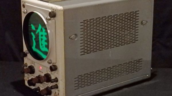
When used in X-Y mode, analog oscilloscopes lend themselves nicely to vector-based graphics, which is the approach [Aaron] has taken with previous “Oscilloclock” builds, like the Metropolis Clock. The current work, however, doesn’t use vector graphics, opting instead to turn the scope into the business end of a VGA display. He had previously developed the hardware needed to convert a VGA signal into X- and Y-axis analog outputs, so the bulk of the work was rendering the calligraphy, first in ink and then scanning and processing the results into a file. In keeping with the Japanese theme, [Aaron] chose a rare scope from Nihon Tsushinki Co., Ltd., from 1963. It’s a beautiful piece of equipment and obviously lovingly restored, and with the VGA adapter temporarily connected, the four Japanese characters scroll gracefully up the screen, delivering the uplifting message: “Steady progress, day by day.

[Aaron] sure puts a lot of work into his analog scope builds, which we’ve featured a few times. Check out the clock he made from Grandpa’s old Heathkit scope, or his Tektronic vectorscope clock. And don’t forget about other forms of oscilloscope art — they can make music too, after all.

Elegant Shoji Lamps From Your 3D Printer

The gorgeous Shoji-style lamps you’re seeing here aren’t made of wood or paper. Beyond the LEDs illuminating them from within, the lamps are completely 3D printed. There aren’t any fasteners or glue holding them together either, as creator [Dheera Venkatraman] used authentic Japanese wood joinery techniques to make their components fit together like a puzzle.

While we’re usually more taken with the electronic components of the projects that get sent our way, we have to admit that in this case, the enclosure is really the star of the show. [Dheera] has included a versatile mounting point where you could put anything from a cheap LED candle to a few WS2812B modules, but otherwise leaves the integration of electronic components as an exercise for the reader.

All of the components were designed in OpenSCAD, which means it should be relatively easy to add your own designs to the list of included panel types. Despite the colorful details, you won’t need a multi-material printer to run them off either. Everything you see here was printed on a Prusa i3 MK3S in PETG. Filament swaps and careful design were used to achieve the multiple colors visible on some of the more intricate panels.

If the timeless style of these Japanese lanterns has caught your eye, you’ll love this beautiful sunrise clock we covered last year.

Zen And The Art Of Japanese Tea Robots

In Japan, tea ceremony (cha-dou) is revered as a way to a gain deeper insights into life and philosophy. Traditional Japanese tea ceremony practitioners put in long hours to master the intricacies and details of pouring tea. The road to becoming a tea master is crucial as it develops the practitioner’s mental state as well as physical technique.

However if you don’t have time to master the “way of tea”, then you can build a bot and automate your zen experience. That’s exactly what the people at Ano Labs did when they built their Japanese Tea Ceremony Robot #151A.

Continue reading “Zen And The Art Of Japanese Tea Robots”

I Am An Iconoscope

We’d never seen an iconoscope before. And that’s reason enough to watch the quirky Japanese, first-person video of a retired broadcast engineer’s loving restoration. (Embedded below.)

Quick iconoscope primer. It was the first video camera tube, invented in the mid-20s, and used from the mid-30s to mid-40s. It worked by charging up a plate with an array of photo-sensitive capacitors, taking an exposure by allowing the capacitors to discharge according to the light hitting them, and then reading out the values with another electron scanning beam.

The video chronicles [Ozaki Yoshio]’s epic rebuild in what looks like the most amazingly well-equipped basement lab we’ve ever seen. As mentioned above, it’s quirky: the iconoscope tube itself is doing the narrating, and “my father” is [Ozaki-san], and “my brother” is another tube — that [Ozaki] found wrapped up in paper in a hibachi grill! But you don’t even have to speak Japanese to enjoy the frame build and calibration of what is probably the only working iconoscope camera in existence. You’re literally watching an old master at work, and it shows.

Continue reading “I Am An Iconoscope”

Learn To Translate IR Codes And Retransmit Using Arduino

[Dave Jones] from EEVBlog.com takes “Arduino fan boys” off the garden path getting down and dirty with different methods to capture, evaluate and retransmit IR remote control codes. Capturing and reproducing IR remote control codes is nothing new, however, [Dave] carves his own roads and steers us around some “traps for young players” along the way.

[Dave] needed a countdown timer that could remotely start and stop recording on his Cannon video camera, which he did with simplicity in a previous EEVBlog post using a commercial learning remote control unit. The fans demanded better so he delivered with this excellent tutorial capturing IR codes on his oscilloscope from an IR decoder (yellow trace) as well as using an IR photo transistor (blue trace) which showed the code inclusive of 38 KHz carrier frequency. Either capture method could easily be used to examine the transmitted code. The second lesson learned from the captured waveforms was the type of code modulation being used. [Dave’s] remote transmitted NEC (Japanese) pulse length encoding — which can be assertaind by referencing the Infrared Remote Control Techniques (PDF). Knowing the encoding methodology it was trivial to manually translate the bits for later use in an Arduino transmitter sketch. We find it amazing how simple [Dave] makes the process seem, even choosing to write his own sketch to reproduce and transmit the IR codes and carrier instead of taking the easy road looking for existing libraries.

A real gem of knowledge in the video was when it didn’t work! We get to follow along as [Dave] stumbles before using a Saleae Logic analyzer to see that his transmitter was off frequency even though the math in his sketch seemed correct. Realizing the digital write routine was causing a slowdown he fudged his math to make the needed frequency correction. Sure, he could have removed the performance glitch by writing some custom port control but logic dictates using the fastest and simplest solution when hacking a one-off solution.

[Dave’s] video and links to source code after the break.

Continue reading “Learn To Translate IR Codes And Retransmit Using Arduino”