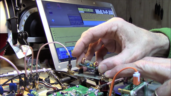
The Simplest FT8 Transceiver You’ll Ever Build

Probably the most interesting facets of amateur radio in 2021 lie in the realm of digital modes. Using the limitless possibilities of software defined radios has freed digital radio communication from the limits of what could be done with analogue electronics alone, and as a result this is a rare field in which radio amateurs can still be ahead of the technological curve. On of these newer digital modes is FT8 created by the prolific [Joe Taylor K1JT].

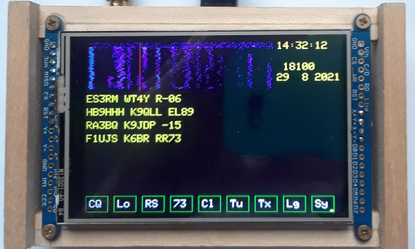
And it’s for this  mode that [Charles Hill] has created an easy-to-build transceiver. Its brains are aTeensy 3.6, while the receive side is a Si4735 receiver chip and the transmitter is a Si5351 programmable clock chip driving a Mini-Circuits GVA84 power amplifier with an appropriate filter. The interface is via a touchscreen display. It relies on existing work that applies a patch on-the-fly to the Si4735 receiver chip for SSB reception, and another project for the FT8 software.

The charm of this transceiver is that it can be assembled almost in its entirety from modules. Some radio amateurs might complain that homebrew radios should only use the most basic of components assembled from first principles, but the obvious answer to that should be that anything which makes radio construction easier is to be welcomed. If the 100 mW output power seems a bit low it’s worth remembering that FT8 is a weak signal mode, and given the right propagation conditions the world should be able to hear it despite the meagre output.

We’ve featured quite a few radios using the Si47XX series, which can be made into very tidy receivers indeed.

This Commodore 16 Is An NTSC One… No, Wait, It’s A PAL One!

We’re used to our computers being powerful enough in both peripheral and processing terms to be almost infinitely configurable under the control of software, but there was a time when that was not the case. The 8-bit generation of home computers were working towards the limits of their capability just to place an image on a TV screen, and every component would have been set up to do just the job it was intended for. Thus when different countries had different TV standards such as the mostly-European PAL and the mostly-American NTSC, there would have been different models of the same machine for each market. The Commodore 16 was just such a machine, and [Adrian Black] has modified his NTSC model with a custom ROM, an Arduino and an Si5351 clock generator to be switchable between the two.

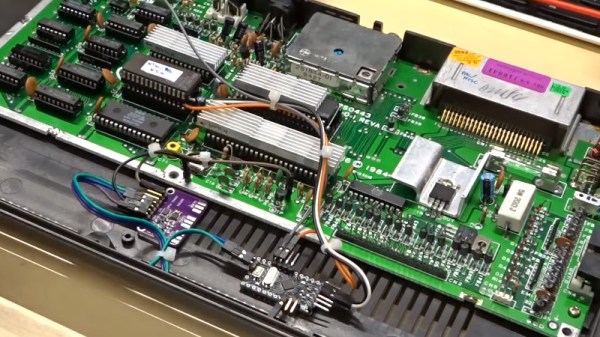
The differences between a PAL and NTSC C16 are two-fold. The clock for the video chip is of a different frequency, and the ROM contents differ too. [Adrian]’s machine therefore has a larger ROM containing both versions which are switchable via one of the upper address lines. A couple of tracks cut in the crystal oscillator circuit allow him to inject a new clock from the Si5351 module, and and Arduino controls everything. The appropriate ROM and clock are selected via a very simple interface, the reset button is captured and while a short press still resets the computer a long one switches the mode.

Despite having its principal engineer, [Bil Herd] as a colleague here at Hackaday, it’s sad that we don’t see as many Commodore 16s as we should. A recent feature showed a 64k C16, but didn’t make it into a C64.

Continue reading “This Commodore 16 Is An NTSC One… No, Wait, It’s A PAL One!”

EBay Modules And Custom PCBs Make A Plug And Play Ham Transceiver

Many of us have fond memories of our introduction to electronics through the “200-in-1” sets that Radio Shack once sold, or even the more recent “Snap Circuits”-style kits. Most of eventually us move beyond these kits to design our circuits; still, there’s something to be said for modular designs. This complete amateur radio transceiver is a great example of that kind of plug and play construction.

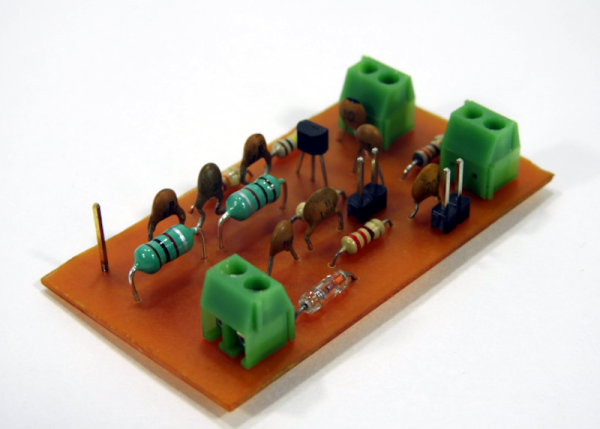
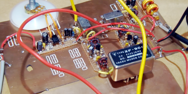
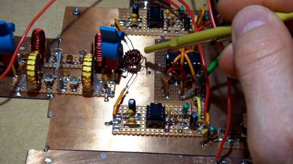
The rig is the brainchild of [jmhrvy1947], who set out to build a complete transceiver using mostly eBay-sourced modules. Some custom PCBs are used, but those are simple boards that can be etched and drilled easily. The transceiver is only for continuous-wave (CW) use, which would normally mean you’d need to know Morse, but thanks to some clever modifications to open-source apps like Quisk and FLDigi, Morse can be received and sent directly from the desktop. That will no doubt raise some hackles, but we think it’s a great way to learn code. The rig is QRP, or low power, transmitting only 100 mW with the small power amp shown. Adding eBay modules can jack that up to a full 100 Watts, which also requires adding a 12-volt power supply, switchable low-pass filters, a buck-boost converter, and some bandpass filters for band selection. It ends up looking very experimental, but it works well enough to make contacts.

We really like the approach here, and the fact that the rig can be built in stages. That makes it a perfect project for our $50 Ham series, which just kicked off. Perhaps we’ll be seeing it again soon.

Continue reading “EBay Modules And Custom PCBs Make A Plug And Play Ham Transceiver”

Portable Ham Radio Design Fosters Experiments

[Charlie Morris] has been busy building a portable ham radio rig and documenting his progress in a series of videos. You can see the first one below. There’s four parts (more if you count things like part 4 and part 4a as two parts) so far and it is always interesting to see inside a build like this, where the choices and tradeoffs are explained.

The first part covers the Si5351 VFO and the associated display. There’s very little to the VFO other than off-the-shelf modules including an Arduino. You can also see the portable Morse code key which is actually a micro switch. The second part experiments with audio amplifiers. [Charlie] looked at the NE5534 vs discrete amplifiers. He was shooting for lowest current draw that was usable. Other parts discuss the RF amplifier and the receiver. Despite the VFO, there is quite a bit of non-module parts by the time things start shaping up.

Continue reading “Portable Ham Radio Design Fosters Experiments”

Homebrew SDR Ham Radio In 9 Parts

It used to be homebrew ham gear meant something simple. A couple of active devices that could send CW. Maybe a receiver with a VFO. But only the most advanced builders could tackle a wide range SSB transceiver. Today, that goal is still not trivial, but it is way easier due to specialty ICs, ready access to high-speed digital signal processing, and advances in software-defined radio techniques. [Charlie Morris] decided to build an SSB rig that incorporated these technologies and he shared the whole process from design to operation in a series of nine videos. You can see the first one below.

The NE612 is a child of the popular NE602 chip, which contains a Gilbert-cell mixer, and an oscillator that makes building a receiver much easier than it has been in the past. The chips are set up as direct conversion receivers and feed a Teensy which does the digital signal processing on the recovered audio.

Continue reading “Homebrew SDR Ham Radio In 9 Parts”

Teensy 3.1 Controlled VFO

[Tom Hall], along with many hams around the world, have been hacking the Silicon Labs Si5351 to create VFOs (variable frequency oscillators) to control receivers and transmitters. You can see the results of his work in a video after the break.

vfo board[Tom] used a Teensy 3.1 Arduino compatible board, to control the Si5351 mounted on an Adafruit breakout board. An LCD display shows the current frequency and provides a simple interface display for changing the output. A dial encoder allows for direct adjustment of the frequency. The ham frequency band and the frequency increment for each encoder step are controlled by a joystick. When you get into the 10 meter band you definitely want to be able to jump by kHz increments, at least, since the band ranges from 28 MHz to 29.7 MHz.

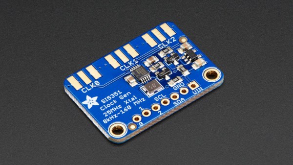
So what is the Si5351? The data sheet calls it an I2C-Programmable Any-Frequency CMOS Clock Generator + VCXO. Phew! Let’s break that down a bit. The chip can be controlled from a microprocessor over an I2C bus. The purpose of the chip is to generate clock outputs from 8 kHz to 160 MHz. Not quite any frequency but a pretty good range. The VCXO means voltage controlled crystal oscillator. The crystal is 25 MHz and provides a very stable frequency source for the chip. In addition, the Si5351 will generate three separate clock outputs.

[Tom] walks through the code for his VFO and provides it via GitHub. An interesting project with a lot of the details explained for someone who wants to do their own hacks. His work is based on work done by others that we’ve published before, which is what hacking is all about.

Continue reading “Teensy 3.1 Controlled VFO”

Polyakov Direct Digital Synthesis Receiver

Direct conversion receivers are popular among ham radio operators and others who build radios. Suppose you want to listen to a signal at 7.1 MHz. With a direct conversion receiver, you’d tune a local oscillator to 7.1 MHz, and mix it with the incoming signal. The resulting sum and differences of the input frequencies will include the audio of an AM signal on the desired frequency.

Continue reading “Polyakov Direct Digital Synthesis Receiver”