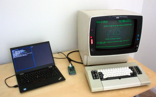
We like to talk about how most of our computers today would have been mainframes a scant 40 or 50 years ago. Because of that, many people who want to run IBM mainframes such as the IBM 360 or 370 use the Hercules emulator to run the big iron on their PCs. However, mainframe IBM computers used an odd style of terminal and emulating it on a PC isn’t always as satisfying. At least, that’s what [lowobservable] thought, so he decided to get a 3270 terminal working with Hercules.
Back in the bad old days of computing, there were two main styles of terminals. Some companies, for example DEC, essentially used terminals as a “glass teletype.” That is, the screen was an analog of a roll of paper — more or less — and the keyboard immediately sent things to the remote system. However, companies like IBM and HP favored a different approach. Their terminals dealt with screens full of data. The terminal was smart enough to let you fill in forms, edit text on the screen, and then you’d send the entire screen in one gulp. Both systems had pros and cons, but — as you might expect — the screen-oriented terminals were more complex.
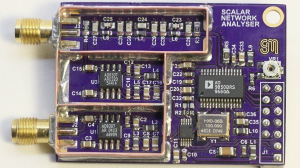
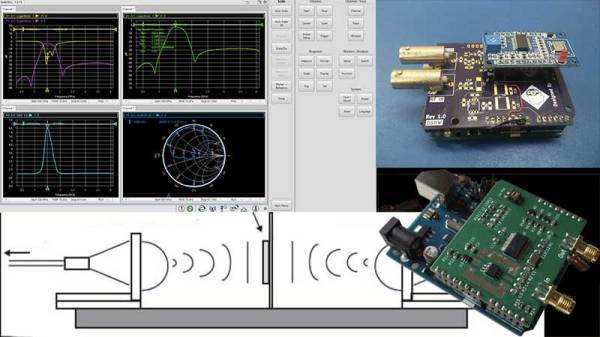
[Steven Merrifield] built his own Scalar Network Analyzer and it’s a beauty! [Steve]’s SNA has a digital pinout matching a Raspberry Pi, but any GPIO could be used to operate the device and retrieve the data from the ADC. The design is based around a few tried and true chips from Analog Devices. He’s taken some care to design it to be nice and accurate which is why he’s limited it to 1kHz to 30Mhz. We think it’s quite a fetching board once the shielding is in place.
We’ve covered network analyzers and their usefulness before. If you want to know how, for example, a mystery capacitor from your junk bin will respond to certain frequencies, a network analyzer could tell you. We’ve even taken a stab at hacking together our own.
There is more documentation on his website as well as some additional example curves. The board is easily ordered from OSHpark and the source code is available for review.
Congratulations and thank you go to Theodore Yapo for authoring the first paper to complete the peer review process for the Hackaday Journal. You can read the standalone paper here; it will be included in the first volume of the Hackaday Journal officially released later this year.
The Hackaday Journal is an open access, peer reviewed journal that seeks to ensure hard-won domain knowledge is preserved and made available for the benefit of all. Before jumping into Ted’s topic, please take a moment to consider submitting your own paper for the journal.
Paper Submissions Wanted
We have other submissions in the pipleline now but we still need more papers to round out the first volume of the Hackaday Journal. Please consider authoring a paper on any creative research, engineering, or entertaining discovery in the areas of interest to the Hackaday community. The full name of our journal is the Hackaday Journal of What You Don’t Know — it will be a tome of infinite appeal to any who seek to broaden their minds in the engineering space. But for that to happen we need you to share your knowledge.
We are in an age of unparalleled opportunity for individuals and small teams to make interesting discovery. You should not need to be working on a degree to have your findings published, but of course students and faculty are encouraged to submit their papers. Do not hesitate to get in touch with us about topics you want to write about.
Scalar Network Analyzer Leakage Correction by Theodore Yapo
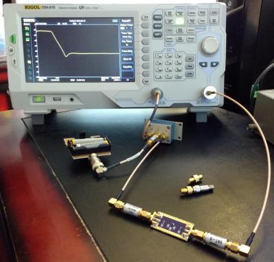
Low-pass filter being tested by a Rigol DSA-815 using the phase shifting correction technique
The title of Ted’s paper is a mouthful and the subject material wades into radio frequency knowledge with gusto. We applaud him, and the peer reviewers, for the attention to detail while moving toward publication.
In his work, Ted finds an interesting opportunity to get more performance out of relatively inexpensive bench equipment used to characterize RF components. This task is often reserved for Vector Network Analyzers (VNA) but with a heafty price tag these tools aren’t available to everyone. Spectrum Analyzers with Tracking Generators (SA/TG) have come onto the market, but especially with early versions, there is a leakage problem that causes inaccuracy. Ted found a simple technique that can correct for the leakage.
The solution is based on phase shifting the measurement. Starting with a properly calibrated machine, Ted uses a small board he built to electronically shift the phase of the Tracking Generator where the leakage is a problem. The signal is first measured, then measured again with a phase shift of 180 degrees. This effectively cancels out the error while preserving the signal being measured.
This paper goes into great technical detail in the RF domain. It is worth noting that the Hackaday Journal is open to discovery on multiple topics and levels of complexity. Don’t let what you think is a simple, useful idea go unpublished. We’re interested in a wide range of the simple, the obscure, and the frighteningly technical as long as the ideas of both novel and well supported.
This is Your Journal
You, yes you reading this right now, embody a movement of inventive and curious people working both inside and outside of formal academic structures. This is our time to contribute to the knowledge base of humanity. Pour yourself a refreshing beverage, saddle up your headphones, crack those knuckles, and let the writing process begin. Let us now what we don’t know. Submit your paper now.
Instrumentation has progressed by leaps and bounds in the last few years, however, the fundamental analysis techniques that are the foundation of modern-day equipment remain the same. A network analyzer is an instrument that allows us to characterize RF networks such as filters, mixers, antennas and even new materials for microwave electronics such as ceramic capacitors and resonators in the gigahertz range. In this write-up, I discuss network analyzers in brief and how the DIY movement has helped bring down the cost of such devices. I will also share some existing projects that may help you build your own along with some use cases where a network analyzer may be employed. Let’s dive right in.
Network Analysis Fundamentals
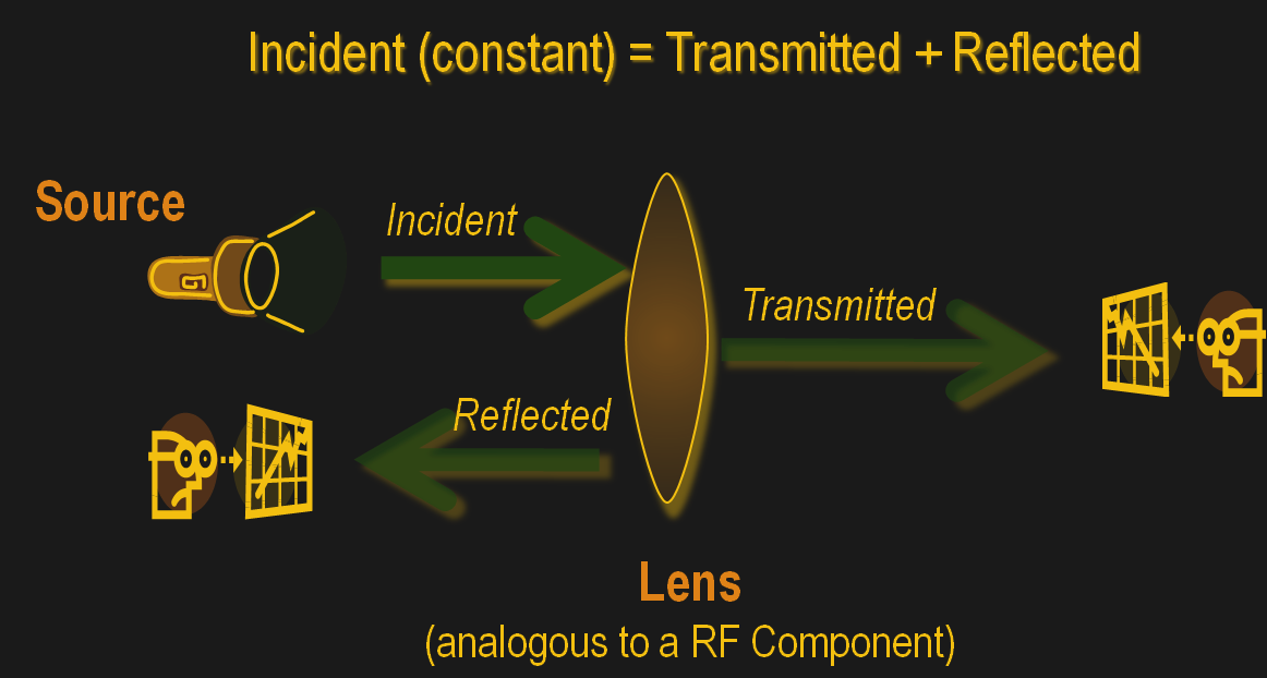
As a conceptual model, think of light hitting a lens and most of it going through but part of it getting reflected back.
The same applies to an electrical/RF network where the RF energy that is launched into the device may be attenuated a bit, transmitted to an extent and some of it reflected back. This analysis gives us an attenuation coefficient and a reflection coefficient which explains the behavior of the device under test (DUT).
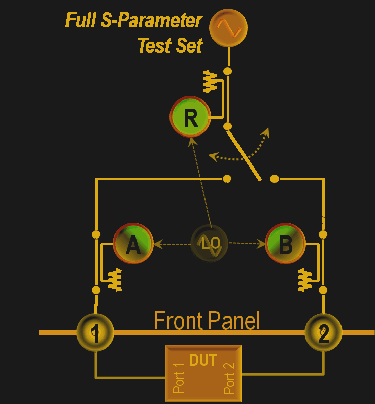
Of course, this may not be enough and we may also require information about the phase relationship between the signals. Such instruments are termed Vector Network Analysers and are helpful in measuring the scattering parameters or S-Parameters of a DUT.
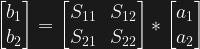
The scattering matrix links the incident waves a1, a2 to the outgoing waves b1, b2 according to the following linear equation: .
The equation shows that the S-parameters are expressed as the matrix S, where and denote the output and input port numbers of the DUT.
This completely characterizes a network for attenuation, reflection as well as insertion loss. S-Parameters are explained more in details in Electromagnetic Field Theory and Transmission Line Theory but suffice to say that these measurements will be used to deduce the properties of the DUT and generate a mathematical model for the same.
General Architecture
As mentioned previously, a simple network analyzer would be a signal generator connected and a spectrum analyzer combined to work together. The signal generator would be configured to output a signal of a known frequency and the spectrum analyzer would be used to detect the signal at the other end. Then the frequency would be changed to another and the process repeats such that the system sweeps a range of frequencies and the output can be tabulated or plotted on a graph. In order to get reflected power, a microwave component such as a magic-T or directional couplers, however, all of this is usually inbuilt into modern-day VNAs. Continue reading “Network Analysers: The Electrical Kind”→


 .
.