Just in case you imagine that those of us who write for Hackaday are among the elite of engineering talent who never put a foot wrong and whose benches see a succession of perfectly executed builds and amazing hacks, let me disabuse you of that notion with an ignominious failure of my own.
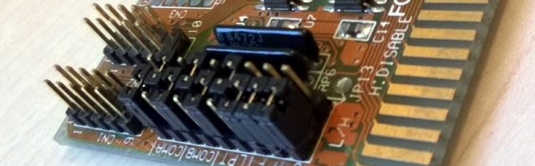
I was building an electronic kit, a few weeks ago. It’s a modular design with multiple cards on a backplane, though since in due course you’ll see a review of it here I’ll save you its details until that moment. In my several decades of electronic endeavours I have built many kits, so this one as a through-hole design on the standard 0.1″ pitch should have presented me with no issues at all. Sadly though it didn’t work out that way.
Things started to go wrong towards the end of the build, I noticed that the temperature regulator on my soldering iron had failed at some point during its construction. Most of it had thus been soldered at a worryingly high temperature, so I was faced with a lot of solder joints to go over and rework in case any of them had been rendered dry by the excessive heat.
In due course when I powered my completed kit up, nothing worked. It must have been the extra heat, I thought, so out came the desolder braid and yet again I reworked the whole kit. Still no joy. Firing up my oscilloscope I could see things happening on its clock and data lines so there was hope, but this wasn’t a kit that was responding to therapy. A long conversation with the (very patient) kit manufacturer left me having followed up a selection of avenues, all to no avail. By this time a couple of weeks of on-and-off diagnostics had come and gone, and I was getting desperate. Somehow I’d cooked this thing with my faulty iron, and there was no way to find the culprit.
KiCAD has been making leaps and bounds recently, especially since CERN is using it almost exclusively. However, while many things are the same, just enough of them are different from our regular CAD packages that it’s hard to get started in the new suite.
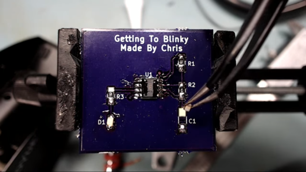
[Chris Gammell] runs Contextual Electronics, an online apprenticeship program which goes from concept to assembled electronics covering everything in between. To take the course you pay a nominal fee, but [Chris] posted a very excellent ten-part video series made during the last run of classes which you can watch without charge. The videos go through the basics of KiCAD while hitting the major points to consider when designing and manufacturing your electronics.
The project [Chris] chose is a simple circuit that blinks an LED with a 555. The first videos cover navigating KiCAD’s component schematic editor and library system. Next comes creating circuit schematics and component footprint creation. [Chris] covers PCB layout, the generation of Gerber files, and finally ordering the design from OSH Park — the purveyors of purple boards we’ve come to know and love. The series finishes up with simulating the circuit in LTSpice, ordering the parts, and finally soldering and debugging of the board. If all goes correctly you should now have a single blinking LED.
If the bright summer sun is burning your delicate skin, and you’d rather be locked inside with solder fumes, add this to your watch list now!
Lulzbot’s TAZ 6 has been released. Lulzbot’s printers consistently place in the top three of any 3D printing list, and the TAZ 6 will likely be no exception. [James Bruton] was one of the lucky ones who got a review unit, and first looks are promising. The TAZ 6 has the auto bed leveling found in the Lulzbot Mini, and a ‘power tower’ for all the electronics. There are completely unconfirmed rumors (or someone told me and I forgot who) that the power tower will be available separately at some point.
The most impressive circuit we’ve seen this weekmonth year is the dis-integrated 6502. It’s a discrete 6502 CPU, about a square foot in size. It’s slow, but it works. RAM and ROM is easy to make embiggened, which means someone needs to build a dis-integrated 6522 VIA. Who’s game?
[Jeremy Cook] wanted to learn another CAD package, in this case Onshape. Onshape is the ‘first cloud-only CAD package’, which has one huge bonus – you can run it anywhere, on anything – and one huge minus – it’s in the cloud. He designed a bicycle cupholder.
Last week, several thousand Raspberry Pi Zeros shipped out to retailers in the US and UK. For a time, Pi Zeros were in stock in some online stores. Now? Not so much. Where did they all go? eBay, apparently. It’s called arbitrage, and it’s the only risk-free form of investment.
Remember those ‘bed of nails’ toys, that were basically two sheets of plastic, with hundreds of small pins able to make 3D impressions of your face and hands. No, there is no official name for these devices, but here’s a Kickstarter for a very clever application of these toys. You can use them to hold through hole parts while soldering. Brilliant.
You should not pay attention to 3D printers on Kickstarter. Repeat after me: you should not give money to 3D printers on Kickstarter. Here’s a 3D printer on Kickstarter, promising a 3D printer for $74. I own several hats, and will eat one if this ships by next year.
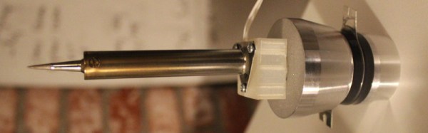
One of the most interesting facets of our community of hackers and makers comes from its never-ending capacity to experiment and to deliver new technologies and techniques. Ample demonstration of this came this morning, in the form of [Hunter Scott]’s Hackaday.io project to create an ultrasonic soldering iron. This is a soldering technique in which the iron is subjected to ultrasonic vibrations which cavitate the surface of the materials to be soldered and remove any oxides which would impede the adhesion of the solder. In this way normally unsolderable materials such as stainless steel, aluminium, ceramic, or glass can be soldered without the need for flux or other specialist chemicals. Ultrasonic soldering has been an expensive business, and [Hunter]’s project aims to change that.
This iron takes the element and tip from a conventional mains-powered soldering iron and mounts it on the transducer from an ultrasonic cleaner. The transducer must be given an appropriate load which in the case of the cleaner is furnished by a water bath, or it will overheat and burn out. [Hunter]’s load is just a soldering iron element, so to prevent transducer meltdown he keeps the element powered continuously but the transducer on a momentary-action switch to ensure it only runs for the short time he’s soldering. The project is not quite finished so he’s yet to prove whether this approach will save his transducer, but we feel it’s an interesting enough idea to make it definitely worth following.
This is the first ultrasonic soldering project we’ve featured here at Hackaday. We have however had an ultrasonic plastic welder before, and an ultrasonic vapour polisher for 3D prints. It would be good to think this project could spark a raft of others that improve and refine DIY ultrasonic soldering designs.
Everyone goes through a few phases during their exploration of electrons, and nowhere is this more apparent than the choice of soldering iron. The My First Soldering Iron™ is an iron that plugs directly into the wall, and doesn’t have temperature control. They’re cheap, and electronics isn’t for everyone, giving the quitters the opportunity to take up woodburning as a hobby. The next step up is a temperature controlled iron, probably an Aoyue or Hakko. The best soldering iron? You’re looking at a Metcal or Weller, and your wallet will become a few hundred dollars lighter.
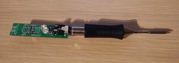
Your My First Soldering Iron™ need not be terrible, though. For his project for The Hackaday Prize, [HP] is working on a soldering iron that is cheap, accurate, and uses the very nice Weller RT tips. No, it’s not as good as a Metcal or proper Weller, but it’s good enough for some fine soldering work and will give the Aoyues and Hakkos a run for their money.
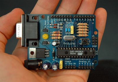
If price is a reasonable measure of the quality of a soldering iron, the irons that use these Weller RT tips are the best irons around. The tips, though, are pretty cheap: about $30, which gets you a heater and thermistor and not much else. There have been numerous reverse engineering efforts for this iron ([1] and [2]), and even a few Arduino-based circuits that replicate the functionality of the Weller base unit.
[HP] is going in a different direction to heat these iron tips. Instead of building a big box to hold the electronics, he’s building everything into the handle of the soldering iron. With brains donated from an ATMega168, a few op-amps, MOSFETS, and a single power jack, [HP] can heat up this soldering iron tip in a compact, hand-held unit.
For his Hackaday Prize entry, [HP] did a rundown of soldering pen in a video. You can check that out below.
As a hackspace member, it’s easy to fall into the belief that your own everyday skills are universal. Soldering for example. You’ve handled an iron since you were a youngster, the solder bends to your will as a matter of course, and since you see your fellow makers doing the same thing you might imagine that it’s a universal hackspace skill. Everyone can do it, can’t they?
Of course, they can’t. If you weren’t lucky enough to have a parent who tolerated your occasional propensity for acquiring burns on your fingers then you probably won’t have that innate experience with an iron. This extends to people you might expect to have those skills, indeed as an electronic engineering student a couple of decades ago your scribe was surprised to find that the ability to solder was her hotly tradeable skill, amazingly even a lot of EE students couldn’t solder.
So the ability to solder is not as universal as we might expect, and your hackspace will attract plenty of people for whom it is an as-yet-unknown art. What do you do about it? If you are Vancouver Hackspace, you run a workshop whose participants are introduced to soldering through building a simple AM radio. The kit itself is not too special, it looks like one of the Elenco educational kits, but it is what the workshop represents that is important. A hackspace lives or dies by how it shares its skills, and Vancouver’s workshop is a fantastic piece of community engagement. We’d like to see more spaces doing this kind of thing.
So, perhaps it’s time to put our money where our mouth is. How difficult would it be to run a hackspace soldering workshop for the uninitiated? Assuming your space is used to the mechanics of running events, the challenge is to find for each participant a soldering iron, some solder, and a radio or other kit without breaking the bank. An ideal budget from where this is being written in the UK would be £20 (about $29), into which a Chinese kit from AliBaba or similar and a cheap iron kit could be fitted. Some work to decipher the Chinese instructions with the help of an overseas student member and to write an English manual, and we’d be ready to go. If this comes together we’ll report back on whether the non-solderers of our hackspace successfully learned the craft.
If you are lucky enough to encounter a piece of homebrew electronics from the 1950s, the chances are that under the covers the components will be assembled on solder tags, each component with long leads, and chassis-mounted sockets for tubes. Easy to assemble with the most agricultural of soldering irons.
Open up a home build from the 1960s or early 1970s, and you might find the same passive components alongside germanium transistors mounted through holes in a curious widely spaced stripboard or even a home-made PCB with chunky wide tracks.
Solder tags aplenty in a commercial transmitter from the early 1960s
Cutting-edge 1970s homebrew
By the late 1970s and early 1980s you would find a more familiar sight. Dual-in-line ICs through-hole on 0.1″ spaced stripboard, and home-made PCBs starting to appear on fibreglass board. Easy to use, easy to solder. Familiar. Safe. Exactly what you’ll see on your breadboard nearly forty years later, and still what you’ll see from a lot of kit manufacturers.
But we all know that progress in the world of electronic components has not stood still. Surface-mount components have a history going back to the 1960s, and started to appear in consumer equipment from the end of the 1980s. More components per square inch, smaller, cheaper devices. Nowadays they are ubiquitous, and increasingly these new components are not offered in through-hole versions. Not a problem if your experiments are limited to the 741 and the 555, but something that rather cramps your style if your tastes extend to novel sensors for a microcontroller, or RF work.
This development has elicited a range of reactions. Many people have embraced the newer medium with pleasure, and the Hackaday.io project pages are full of really clever SMD projects as a result. But a significant number have not been able to make the jump to SMD, maybe they are put off by the smaller size of SMD components, the special tools they might require, or even the new skills they’d have to learn. When you sell a kit with SMD components these are the reactions you will hear from people who like the kit but wish it was available in through-hole, so this article is for them. To demystify working with SMDs, and to demonstrate that SMD work should be within the grasp of almost anyone who can wield a soldering iron.
But They’re So Tiny!
Tiny SMDs – fortunately most of which you will not have to worry about.
It’s likely to be the first reaction from a lifelong through-hole solderer. SMD parts are often very small indeed, and even those with larger packages can have leads that seem as numerous and thin as the hairs on a cat when seen with the rabbit-in-the-headlights panic of the uninitiated.
But it is important to take a step back and understand that not all SMDs are created equal. Some of them are grain-of-sand tiny and only hand-solderable by those with God-like powers, but plenty of devices are available in SMD packages large enough for mere mortals.
So don’t worry when you look at a board covered with grain-of-dust-sized components. Very few people could attempt that level of construction, your scribe certainly can’t. (We await commenters claiming to routinely hand-solder thousand-pin BGAs and 01005 chip components with anticipation, however such claims are useless without proof.)
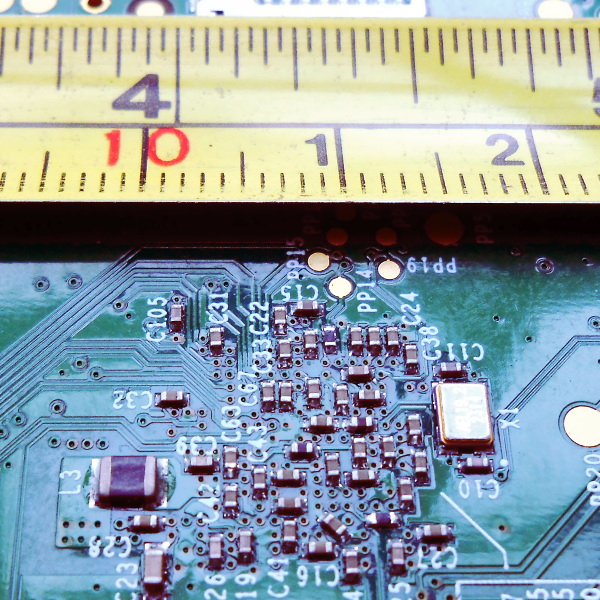
Instead, concentrate on the SMD packages you can handle. SMD chip component packages are refered to by a number that relates to their dimension. Confusingly there are both metric and imperial versions of the scheme, but the format is the same: length followed by width.
Consider the picture above with the PCB and the tape measure, it’s the underside of a Raspberry Pi model B+, and will have been assembled by a robotic pick-and-place machine. The majority of the components are very tiny indeed, but you will notice L3 as the black component towards the bottom left that looks huge compared to its neighbours. That package is a “1008”, 0.1 inches long by 0.08 inches wide. It’s still tiny, but imagine picking it up with a pair of tweezers under a magnifying glass. Not so bad, is it. You’ve probably handled plenty of things in that size range before, do SMD parts seem so scary now? The larger components – 0805, 1008, and 1206 – are surprisingly within the grasp of the average maker.
But I need all sorts of special tools!
Retro Populator, a homebrew pick-and-place machine we featured back in 2014
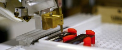
In a commercial environment an SMD device will be assembled by machine. Glue or solder paste will be printed in the relevant parts of the board, and a robotic pick-and-place machine will retrieve components from their tape packaging and automatically place them in their correct orientations. The board will then be soldered all-at once, either in a reflow oven or by a wave soldering machine.
You’ll also see all manner of commercial kit aimed at the bench-top SMD constructor. Hot air soldering stations or SMD bits for conventional irons, all of which are very useful but come with a hefty price tag.
The good news is that you don’t need any of these special tools to dip your toe into the SMD water. You almost certainly already have everything you need, and if you don’t then very little of what you lack is specifically for SMD work. If you have the following items then you are good to go:
A basic SMD soldering toolkit
A good light source. Even the larger SMDs are still pretty small. Plenty of light ensures you will be able to see them clearly. A good downward pointing desk lamp should suffice. A clear high-contrast surface. Because SMDs can be difficult to see, it helps if they are manipulated over a bright white surface. A fresh sheet of white printer paper on a desk makes a suitable working area. Good hands-free magnification. Unless you are fortunate enough to have amazing eyesight, you will need a decent magnifier to work with surface-mount components. The “Helping hands” type on a stand are suitable. A very small flat-blade screwdriver. You will need this to hold surface-mount components down while you solder them. A good-quality set of precision metal tweezers. You will need these for picking up, manipulating, and turning over surface-mount devices. A fine-tipped soldering iron. If you have a standard fine tipped iron suitable for use with conventional 0.1” pitch through-hole components then you should be well-equipped.
That said there is one special tool that might be worth your consideration. Holding an SMD device while soldering it can sometimes seem like a task that needs three hands, so one or two tools can be found to help. Fortunately this is something you can build yourself. Take a look at the SMD Beak, a weighted arm for example, or your scribe’s spring clamp third hand.
I’m sorry, this is just beyond my soldering skill level
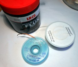
Desolder braid and plenty of flux are your friends.
It is easy to imagine when you are looking at an SMD integrated circuit that its pins are just too small and too close together, you couldn’t possibly solder them by hand. The answer is that of course you can, you simply need to view how you solder them in a different way.
With a through-hole IC you solder each 0.1″ pitch pin individually. It is something of a disaster if you manage to put a solder bridge between two pins, and you race for your desolder pump or braid.
With a surface-mount IC by comparison there is little chance that you as a mere mortal could solder each pin individually, so you don’t even try. Instead you solder an entire row at once with an excess of solder, and remove the resulting huge solder bridge with desolder braid to leave a very tidy and professional-looking job. Surface tension and plenty of flux are your friends, and there is very little soldering skill required that you do not already have if you are an experienced through-hole solderer.
If you can hold it down onto the board and see it clearly with your magnifier if necessary, then it doesn’t matter what the component is, you can solder it. Give it a try, you’ll surprise yourself!
What next?
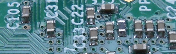
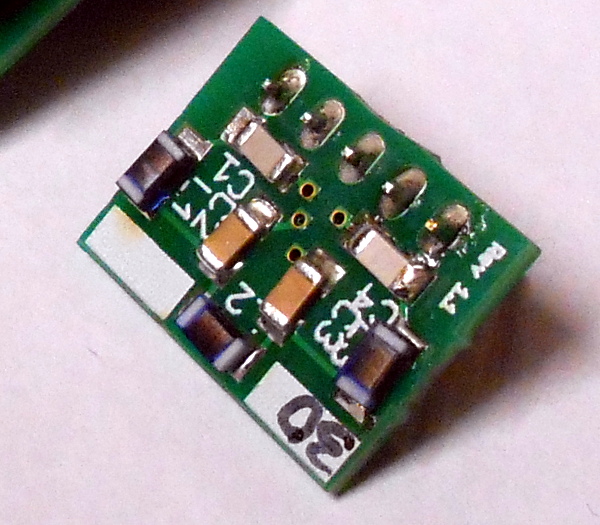
1206 chip discrete components hand-soldered to a PCB
So we hope we’ve convinced you as an SMD doubter, that you have the ability to work with SMDs yourself. What next?
But there is no substitute for practice. Find a scrap board populated with reasonably-sized surface-mount components, and have a go at reworking it. Desoldering its components may be a bit difficult, but you should easily be able to rework the solder joints. Slather an integrated circuit’s pins with flux, and try running a blob of molten solder along them, then removing the excess with desolder braid. The great thing about a scrap board is that it doesn’t matter if you damage it, so you can practice these techniques to your heart’s content until you are satisfied with your new-found skill.
So you’re ready to move forward, and make your first SMD project. Well done! What you do next is up to you. Design your own circuit and get a PCB made, buy a kit, or find an SMD project you like on Hackaday.io with downloadable PCB files and order your own.
Whatever you do, be happy that you’ve conquered your SMD fears, and resolve to be first in the queue to try any new technology in the future!