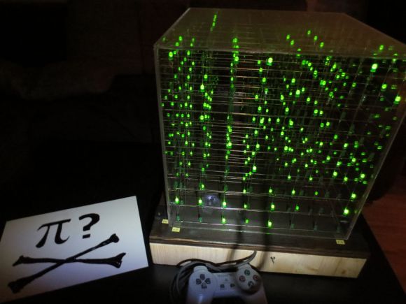
Soldering Small Components For A Video DA

Video DA Board

Video distribution amplifiers are used to amplify a video signal and split it into multiple outputs so multiple displays can be driven. They are also used to correct the gain of an incoming video signal. [Andrew] was having trouble with the video signal from an interferometer, and found the issue was caused by a low output gain. His solution was to build his own video distribution amplifier.

The THS7374 appeared to be the perfect chip for this application. It’s a four channel video amplifier IC, and only requires a few passive components to run. The only problem was the package: a 14 pin TSSOP with 0.65 mm pitch. Not fun to solder by hand, especially if you don’t have a PCB.

[Andrew]’s solution was to build his own breakout out of copper-clad board. He worked under a microscope and cut out a pattern for the part, then soldered 30 AWG wire to the pins to make connections. After cleaning off any copper that could cause a short, the board was working, and the video waveform looked great on an oscilloscope.

After testing, even more gain was needed. [Andrew] ended up cascading two of the amplifiers. This method of prototyping doesn’t look easy, but could be worth it when you need a single board.

BGA Soldering With A Paint Stripper And Stopwatch

Having just received a shiny set of PCBs from the fab-house [Devbisme] needed a way to solder the main chip in place. It has a Ball-Grid Array footprint which is notoriously difficult to populate in a home lab. But he makes it look pretty easy and decided to share a video tutorial of the process.

The main tool he used is the paint stripper (heat gun) seen above. Since he didn’t have his own fancy reflow oven he made things work with the gun as his heat source. First he applies a generous layer of liquid solder flux to the BGA footprint on the board. Next he melts some solder onto the tip of his iron and uses it to tin all of the board’s BGA pads. Then it’s time for the critical step of positioning the chip. He uses vacuum tweezers to set it in place, and traditional tweezers to fine-tune its position. From here he heats with the paint stripper for two minutes, starting far above the board and slowly moving closer, with the reverse at the end of the soldering process. Once cool the board is cleaned with distilled water and blown dry with compressed air. After a visual inspection he finishes the application with a 30 minute stay in a 300 degree oven. We’ve included the video after the break for your convenience.

We’ve seen a similar technique used for replacing a chip on an already populated board.

Continue reading “BGA Soldering With A Paint Stripper And Stopwatch”

Swapping Out Eee PC BGA Chip For 1.6 GHz Upgrade

Personally we find this Ball-Grid Array chip-swap rather horrifying. But if you want to beef up the processor on your 701 Eee PC this is what you’ll need to go through. Not only did [Red Fathom] upgrade to a 1.6 GHz chip, but he managed to get the computer to boot up with the new hardware in place.

BGAs are notoriously hard to solder. This hack pulls it off using just a hot air gun. [Red Fathom] heats the board from the underside until the solder melts and he can pluck off the old chip. He then uses a solder braid and iron to remove extra solder from the footprint. After a little cleanup with a cotton swab and some flux he plops in an Intel Pentium M LV 778. It doesn’t look like he added any solder after the cleaning process. Perhaps he’s relying on the small amount left on the tinned pads of the board?

After the break you can see the soldering process and a video of the new processor booting Xandros.

Continue reading “Swapping Out Eee PC BGA Chip For 1.6 GHz Upgrade”

Know Thy Enemy: Open Vias In BGA Footprints

[Andrew Zonenberg] has crossed a line in his electronic hobby projects. The Ball Grid Array (BGA) is a type of chip footprint which most hobbyists leave to the professionals. But he’s learned the skills necessary to use them in his projects. Recently he ran a test batch to show off his soldering process and illustrate one of the errors a novice might make.

For those that are unfamiliar, the BGA footprint is notoriously difficult to accurately solder because it consists of a large grid of tiny points covering the bottom of the chip. There’s no way to get in there with an iron, so soldering depends on accurate placement of solder paste and chip, as well as a near-perfect reflow cycle. Often times it’s difficult for the professionals too. Many blame the heat-failure of Xbox 360 on the complications of the BGA connects for one of the console’s chips.

For this experiment [Andrew] wanted to show what happens if you include vias in the BGA footprint. It’s fine to do so, as long as they’re capped. But if a standard via is included, capillary action ends up pulling the solder down into the via instead of making a connection with the chip. The image above is a cross-section of one such uncapped via, seen on the far right.

[Thanks George]

DIY Battery Powered Soldering Iron

When it’s time to get started on a project and put our irons in the fire, we usually reach for a nice Weller or Hakko soldering iron. Unfortunately, that isn’t possible when we’re soldering something away from a wall outlet. Portable soldering irons usually range from slightly to completely terrible, and [Adam] thought he could do better. He put together an Instructable for a portable battery-powered soldering iron that’s extremely easy to build.

[Adam]’s project mounts a standard Radio Shack soldering iron tip in an E-10 flashlight bulb socket. Power is provided by 6 Volts of AA batteries, with a small switch added for the obvious safety concerns. Although [Adam] could have added a small project box, he chose to build his entire project around a piece of wood. This is an excellent choice in our humble opinion; wood doesn’t melt, has very low thermal conductivity, and anyone using this iron should be smart enough to turn it off if the handle starts smoking.

While this isn’t the best possible portable soldering iron (we’re partial to the disposable-lighter-fueled torches with a soldering iron attachment), it’s much better than the ColdHeat soldering iron that received consistently bad reviews.

Edit: [Adam] updated his build to be a little safer after this story was posted. We changed the original title pic to reflect this; here’s the old one.

Hackaday Links: January 24, 2012

Open source engraving

[Scott] wanted to do some v-carving with a CNC router, but couldn’t find software to generate GCode that didn’t cost hundreds of dollars. He ended up doing the sensible thing and wrote his own that will generate tool paths from CXF fonts. We’ll be bookmarking this for when our router project is done.

Improving Genesis sound output

Dissatisfied with the sound output on his Sega Genesis, [Drakon] installed a few mods into his console. How much could it really affect the sound? Listen to the video. The changeover happens at 0:50. Impressive. Now if only the chiptune scene would get into Segas.

Yes, we did, and now we’re seeding

Here’s an alternative to Thingiverse: The Pirate Bay has a new category for 3D-printable objects. The best file so far? A 1970 Chevelle. US Copyright law does not protect (most) physical objects, so it’s not illegal. Honestly, we can’t wait for somebody to take this to the courts; It’s sure to be an interesting case. Somebody upload a ship hull design and give the EFF a buzz.

Just be glad it’s not a QFN

[Mikey] was pulling a PDIP ATMega8 out of a socket with pliers and a screwdriver and broke the RESET pin. Ouch. He fixed it by soldering on a lead from a resistor. We’ve all done this before, but [Mikey]’s results look really good. Here’s the gallery.

This might be fake

If you want a second analog stick for your 3DS, you could wait a month and buy a Circle Pad Pro, or install a PSP analog stick. We’re not sure how this would work – the Circle Pad Pro works over IR, and we’re not seeing an IR transmitter on this build. Here’s the source if anyone wants to give this a shot.

A Very Detailed Reflow Oven Build

smd-solder-reflow-oven

If you do a lot of SMD soldering, a reflow oven is the fastest and most efficient way to get all those tiny components attached to your PCB. [Frank Zhao] saw the reflow ovens we featured here over the last few weeks and figured he might as well show off his rig as well. We’re certainly glad he did, because his very thorough writeup is a great stepping stone for anyone looking to construct a reflow oven of their own.

Like many others, he started off with a used toaster oven, modifying it to be controlled directly via the power cable rather than the oven’s dials. He built a small PCB to regulate the oven, which features an ATmega32u4 and thermocouple to keep the temperature in check. Control of the heating element is done using a solid state relay, for which he built his own heatsink.

He studied the reflow profile of the solder he would be using, programming the microcontroller to regulate the heating/cooling process without requiring any user input, aside from turning the oven on.

Check out the video below to see a brief overview of his system, and be sure to swing by his writeup to take a look at all the build details. There are a handful of additional videos along with plenty of pictures there, walking through each step of the process.

Continue reading “A Very Detailed Reflow Oven Build”