It used to be that every well-stocked doomsday bunker had a Geiger counter. These days, you don’t have to have a big tube-based meter. You can inexpensively get a compact digital instrument to handle your radiation detection needs. [DiodeGoneWild] reviews and tears down such a unit from FNIRSI. The case looks like several other similar instruments we’ve seen lately, so presumably, someone is mass-producing these handheld meter cases. You can see the video, below. The meter reads the absolute radioactivity and can also measure cumulative exposure.
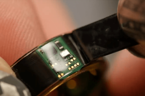
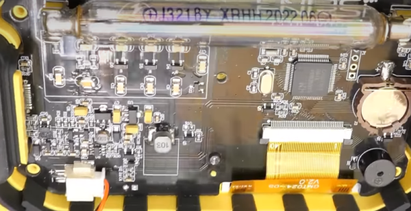
After measuring a few common radioactive items, we get to the teardown. Inside, of course, is an ordinary tube. A few screws reveal a typical rechargeable battery, a fairly simple PCB with a microcontroller and battery backup for the real-time clock. A lot of the board is involved in multiplying voltage up to the several hundred volts required for the Geiger tube.
The other side of the PCB has only buttons, a vibration motor, and, of course, the LCD. We don’t know how you might test the relative accuracy other than comparing it to a known-good meter. The bare tube was, of course, more sensitive without the plastic cover, but that could be calibrated out, too.
A Geiger counter doesn’t have to have a lot of parts. Either way, a surprising number of things will set them off.