Save Money And Have Fun Using IEEE-488

A few months ago, I was discussing the control of GPIB equipment with a colleague. Based on only on my gut feeling and the briefest of research, I told him that the pricey and proprietary GPIB controller solutions could easily be replaced by open-source tools and Linux. In the many weeks that followed, I almost abandoned my stance several times out of frustration. With some perseverance, breaking the problems into bite-sized chunks, and lots of online searching to learn from other people’s experiences, my plan eventually succeeded. I haven’t abandoned my original stance entirely, I’ve taken a few steps back and added some qualifiers.

What is GPIB?

Example of HP-IB block diagram from the 1970s, from hp9845.net

Back in the 1960s, if test equipment was interconnected at all, there weren’t any agreed-upon methods for doing so. By the late 60s, the situation was made somewhat better by card-cage controller systems. These held a number of interface cards, one per instrument, presenting a common interface on the backplane. Although this approach was workable, the HP engineers realized they could significantly improve the concept to include these “bridging circuit boards” within the instruments and replacing the card cage backplane with passive cables. Thus began the development of what became the Hewlett-Packard Interface Bus (HP-IB). The October 1972 issue of the HP Journal introduced HP-IB with two main articles: A Practical Interface System for Electronic Instruments and A Common Digital Interface for Programmable Instruments: The Evolution of a System. Continue reading “Save Money And Have Fun Using IEEE-488”

Multimeters Go Big Screen

We’ve noticed lately that some cheap meters have gone to having big colorful screens. The screens aren’t dot matrix, but still have lots of graphics that could be useful or could be distracting eye candy, depending. The really cheap ones seem more like a gimmick, but [OM0ET] took a look at one that looked like a fair midrange instrument with some useful display features, the GVDA GD128.

A lot of the display shows the current function of the meter. No need for an expensive multiposition switch or rows of interlocking pushbuttons. Many of these new meters also have non-contact voltage sensors, which is handy. Otherwise, it looks like a pretty conventional cheap meter. Continue reading “Multimeters Go Big Screen”

Chip Tester Knows If Your Old Chips Are Working

[Noel’s Retro Lab] has looked at retro chip testers before, but in a recent video you can see below he’s looking at the Chip Tester Pro, a preassembled chip tester for vintage chips, especially those used in Commodore computers. The device looks good on the surface with a form factor like a calculator or cell phone, an LCD display, and a 48 pin ZIF socket.

The user interface is pretty simple. A rotary encoder and a big red button are about it. However, there are also some headers where you have to use jumpers to wire signals to the chip. The firmware gives you specific directions, but it is reminiscent of programming old punchcard machines with jumper wires. Luckily, it looks like you only route the power to the device so you don’t have many wires to connect (usually two or three).

Continue reading “Chip Tester Knows If Your Old Chips Are Working”

Mystery HP Gear Teardown

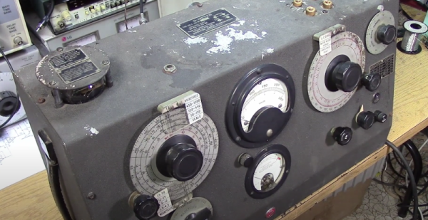
What’s round, has what looks like a vacuum tube in the center, and was made in the 1950s by HP? We don’t know either, but [The Signal Path] restored one and shows us this mystery instrument in a recent video that you can see below. We aren’t going to spoil the surprise over what the device is, but we will share that he does reveal what it is very early in the video, so there’s not much of a tease.

We will, however, give you a few hints. Looking at it, you can guess that it is meant for high voltage use and, in fact, it is rated for up to 25 kV. We’ll also drop the hint that it is made for use with AC, not DC. The shape of the plug at the end of the wire is also a clue, we think.

There isn’t much inside the unusual round case (another clue, by the way), but there are some vintage parts we haven’t seen in quite awhile. One last clue: Why is there a metal rod and ball sticking out of one side of the device?

Honestly, the insides are a bit underwhelming so unlike some teardown videos we’ve seen, the real star of this video is the unusual device more so than its inner workings. If you have a hankering for a more sophisticated HP exploration, check out the HP3458A repair we covered earlier. Or go old school and peek inside an HP 150A.

Continue reading “Mystery HP Gear Teardown”

Custom Isolated Variac Is Truly One Of A Kind

It’s no surprise that many hardware hackers avoid working with AC, and frankly, we can’t blame them. The potential consequences of making a mistake when working with mains voltages are far greater than anything that can happen when you’re fiddling with a 3.3 V circuit. But if you do ever find yourself leaning towards the sparky side, you’d be wise to outfit your bench with the appropriate equipment.

Take for example this absolutely gorgeous variable isolation transformer built by [Lajt]. It might look like a  high-end piece of professional test equipment, but as the extensive write-up and build photographs can attest, this is a completely custom job. The downside is that this particular machine will probably never be duplicated, especially given the fact its isolation transformer was built on commission by a local company, but at least we can look at it and dream.

This device combines two functions which are particularly useful when repairing or testing AC hardware. As a variable transformer, often referred to as a variac, it lets [Lajt] select how much voltage is passed through to the output side. There’s a school of thought that says slowly ramping up the voltage when testing an older or potentially damaged device is better than simply plugging it into the wall and hoping for the best. Or if you’re like Eddie Van Halen, you can use it to control the volume of your over-sized Marshall amplifiers when playing in bars.

Image of the device's internal components.Secondly, the unit isolates the output side. That way if you manage to cross the wrong wire, you’re not going to pop a breaker and plunge your workshop into darkness. It also prevents you from accidentally blowing up any AC powered test equipment you might employ while poking around, such as that expensive oscilloscope, since the devices won’t share a common ground.

Additional safety features have been implemented using an Arduino Uno R3 clone, a current sensor, and several relays. The system will automatically cut off power to the device under test should the current hit a predetermined threshold, and will refuse to re-enable the main relay until the issue has been resolved. The code has been written in such a way that whenever the user makes a configuration change, power will be cut and must be reestablished manually; giving the user ample time to decide if its really what they want to do.

[Lajt] makes it clear that the write-up isn’t meant as a tutorial for building your own, but that shouldn’t stop you from reading through it and getting some ideas. Whether you’re in the market for custom variac tips or just want to get inspired by an impeccably well engineered piece of equipment, this project is a high-water mark for sure.

Vintage Test Equipment Addiction Justified

Recore 3D printer board developer [Elias Bakken] has posted about the automatic test procedure he developed using a stack-up of four (at least) pieces of vintage HP test equipment. In addition, his test jig and test philosophy is quite interesting.

Besides making a bed-of-nails test jig, he also designed a relay multiplexing board to that selects one of the 23 different voltages for measurement. We like his selection of mechanically latching relays in this application — not only does it save power, but it doesn’t subject the test board to any magnetic fields (except when switching state).

In [Elias]’s setup, the unit under test (UUT) actually orchestrates the testing process itself. This isn’t as crazy as it might sound. The processor is highly integrated in one package plus external DRAM. If the CPUs boot up at all, and pass simple self-test routines, there’s no reason not to utilize the on-board processor as the main test control computer. This might be a questionable decision if your processor was really small with constrained resources and connectivity. But in the case of Recore, the processor is a four-core ARM A53 SoC running Debian Linux — an arrangement that itself could well serve as an automated test computer in other projects.

In the video down below, [Elias] walks us through the basic tests, and then focuses on the heart of the Recore board tests: calibrating the input signal conditioning circuits. Instead of using very expensive precision resistors, [Elias] selected more economical 1% resistors to use in the preamp circuitry. The tradeoff here is the need to calibrate each channel, perhaps at multiple temperature points. This is a situation where using a test jig, automated test scripts, and and stack of programmable test equipment really shines.

[Elias] is still pondering some issues he found trying to calibrate thermocouples, so his adventure is not quite over yet. If you are wondering what Recore is, check out this article from back in June. Have you ever used the microprocessor on a circuit board to test itself, either standalone or in conjunction with an external jig? Let us know in the comments below.

Continue reading “Vintage Test Equipment Addiction Justified”

Boat Anchor Nixie Clock Plays The Cold Warrior Role Convincingly

The early Cold War years may have been suffused with existential dread thanks to the never-ending threat of nuclear obliteration, but at least it did have a great look. Think cars with a ton of chrome, sheet steel toys with razor-sharp edges, and pretty much the entire look of the Fallout franchise. And now you can add in this boat anchor of an electromechanical Nixie clock, too.

If [Teti]’s project looks familiar, perhaps it’s because the build was meant as an homage to the test equipment of yore, particularly some of the sturdier offerings from Hewlett-Packard. But this isn’t some thrift store find that has been repurposed; rather, the entire thing, from the electronics to the enclosure, is scratch built. The clock circuit is based on 4000-series CMOS chips and the display uses six IN-1 Nixies. Instead of transistors to drive the tubes, [Teti] chose to use relays, which in the video below prove to be satisfyingly clicky and relaxing. Not relaxing in any way is the obnoxious alarm, which would be enough to rouse a mission control officer dozing in his bunker. [Teti] has a blog with more details on the build, the gem of which is information on how he had the front panel so beautifully made.

We can’t say enough about the fit and finish of this one, as well as the functionality. What’s even more impressive is that this was reportedly [Teti]’s first project like this. It really puts us in mind of some of the great 6502 retrocomputer builds we’ve been seeing lately.

Continue reading “Boat Anchor Nixie Clock Plays The Cold Warrior Role Convincingly”