3D Printing With A Twist

When we think about sending an STL off on the Internet for processing, we usually want someone to print it for us or we want mesh repair. But [Chuck] found an interesting project on GitHub from [Andrew Sink] that will let you add a variable amount of twist to any STL and then return it to you for printing or whatever else you use STLs for. If you don’t get what we mean, check out the video below.

The site that does the work initially loads a little gnome figure if you are too lazy to upload your own model. That’s perfect, though, because the little guy is a good example of why you might want to twist a model. With just a little work, you can make the gnome look in one direction or even look behind him.

[Chuck] shows how to use the tool for artistic effect by twisting his standard cube logo. The result is something that looks like it would be difficult to create, but could hardly be easier. The tool lets you rotate the object, too, so you can get the twist effect in the right orientation for what you want to accomplish. A great little tool for making more artistic 3D prints without learning new software. If you want some fun, you can try the version that uses sound from your microphone to control the twist.

If you’d rather twist in CAD, we can help. If you really want artsy 3D printing, you probably need to learn Blender.

Continue reading “3D Printing With A Twist”

Making Things Square In Three Dimensions

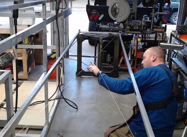
Measure twice, cut once is excellent advice when building anything, from carpentry to metalworking. While this adage will certainly save a lot of headache, mistakes, and wasted material, it will only get you part of the way to constructing something that is true and square, whether that’s building a shelf, a piece of furniture, or an entire house. [PliskinAJ] demonstrates a few techniques to making things like this as square as possible, in all three dimensions.

The first method for squaring a workpiece is one most of us are familiar with, which is measuring the diagonals. This can be done with measuring tape or string and ensures that if the diagonals are equal lengths, the workpiece is square. That only gets it situated in two dimensions, though. To ensure it’s not saddle-shaped or twisted, a little more effort is required. [PliskinAJ] is focused more on welding so his solutions involve making sure the welding tables are perfectly flat and level. For larger workpieces it’s also not good enough to assume the floor is flat, either, and the solution here is to minimize the amount of contact it has with the surface by using something like jack stands or other adjustable supports.

There are a few other tips in this guide, including the use of strategic tack welds to act as pivot points and, of course, selecting good stock to build from in the first place, whether that’s lumber or metal. Good design is a factor as well. We’ve also featured a few other articles on accuracy and precision,

How To Model A Twisted Part In FreeCAD

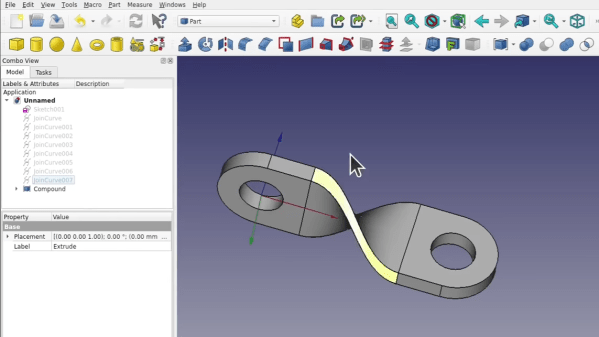
Quick references are handy, but sometimes it’s nice to have a process demonstrated from beginning to end. In that spirit, [Darren Stone] created a video demonstrating how to model a twisted part in FreeCAD, showing the entire workflow of creating the part as a blend of surfaces and curves that get turned into a solid.

FreeCAD is organized using the concept of multiple “workbenches” which are each optimized for different tools and operations, and [Darren] walks through doing the same jobs in a few different ways.

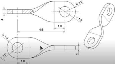
This twisted bracket is a simple part that is nevertheless nontrivial from a CAD perspective, and that makes it a good candidate for showing off the different workbenches and tools.

The video below is also pretty good overall demonstration of what designing a part from a mechanical drawing looks like when done in FreeCAD. As for mechanical drawings themselves, we’ve seen FreeCAD can be used to make those, too.

Continue reading “How To Model A Twisted Part In FreeCAD”