Just over a year ago, FTDI, manufacturers of the most popular USB to serial conversion chip on the market, released an update to their drivers that bricked FTDI clones. Copies of FTDI chips abound in the world of cheap consumer electronics, and if you’ve bought an Arduino for $3 from a random online seller from China, you probably have one of these fake chips somewhere in your personal stash of electronics.
After a year, we have the latest update to FTDI gate. Instead of bricking fake chips, the latest FTDI drivers will inject garbage data into a circuit. Connecting a fake FTDI serial chip to a computer running the latest Windows driver will output “NON GENUINE DEVICE FOUND!”, an undocumented functionality that may break some products.
FTDI gate mk. 1 merely bricked fake and clone chips, rendering them inoperable. Because fakes and clones of these chips are extremely common in the supply chain, and because it’s very difficult to both tell them apart and ensure you’re getting genuine chips, this driver update had the possibility to break any device using one of these chips. Cooler heads eventually prevailed, FTDI backed down from their ‘intentional bricking’ stance, and Microsoft removed the driver responsible with a Windows update. Still, the potential for medical and industrial devices to fail because of a random driver update was very real.
The newest functionality to the FTDI driver released through a Windows update merely injects unwanted but predictable data into the serial stream. Having a device spit out “NON GENUINE DEVICE FOUND!” won’t necessarily break a device, but it is an undocumented feature that could cause some devices to behave oddly. Because no one really knows if they have genuine FTDI chips or not – this undocumented feature could cause problems in everything from industrial equipment to medical devices, and of course in Arduinos whose only purpose is to blink a LED.
Right now, the only option to avoid this undocumented feature is to either use Linux or turn off Windows Update. Since the latter isn’t really a great idea, be prepared constantly roll back the FTDI driver to a known good version.

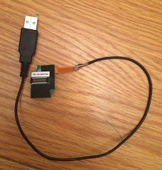 He found a cheap replacement fingerprint scanner on hacker’s heaven, also known as eBay. It had four wires attached to a 16 pin connector. Investigation on the scanner end showed the outer pair were power and ground which made [Serge] suspect it was a USB device. Wiring up a USB connector and trying it the device was recognized but with a lot of errors. He swapped the signal lines and everything was perfect. He had sudo at his finger tip.