Fubarino Contest: FPGA Pong

pong

For [Eric]’s entry for our Fubarino Contest, he went down to very low-level hardware and created Pong on an FPGA.

[Eric] used a Basys 2 FPGA board to create this virtual, logic gate version of Pong. Output is via the VGA port, multiplayer and an AI player is implemented, and all the required mechanics for Pong – collision detection, button and switch input, and score keeping are also in this project.

The Fubarino contest requires an easter egg, of course, so when the score for the left player reaches 13 and the score for the right player reaches 37 (get it? 1337?), the previously square ball turns into an extremely pixeley version of the Hackaday logo. The Hackaday URL is also displayed, thanks to [Eric]’s FP(V)GA module for displaying text on his FPGA board.

The improved Pong ball and URL only appears when the scores are 13-37, making this an extremely well-hidden easter egg. Video of [Eric] demoing his Pong below.


This is an entry in the Fubarino Contest for a chance at one of the 20 Fubarino SD boards which Microchip has put up as prizes!

Continue reading “Fubarino Contest: FPGA Pong”

Build An FPGA Microbee In Three (Not So) Easy Steps

Microbee,_Melbourne_Museum

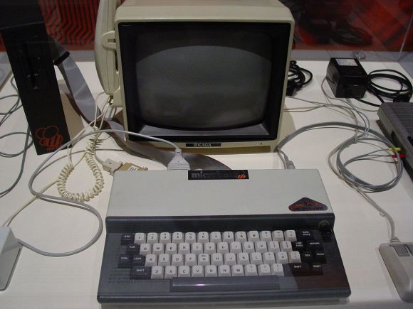
[Brad Robinson] was feeling a bit nostalgic for his Microbee, so he rebuilt it in an FPGA. Not once, but three times. For the uninitiated, the Applied Technology Microbee was a Z80 based computer 1980’s. Designed in Australia, the Microbee did not see much popularity outside its home continent. Even so, the introduction to home computers many Australians was on a Microbee. [Brad] actually wrote several programs for the Microbee, including some games sold by Applied Technology themselves.

Fast forward to 2012, [Brad] is learning FPGAs, and wants to build a Microbee in VHDL. The FPGAbee was born. The first iteration of the FPGAbee began with the CPU, which came from the T80 open source VHDL Z80 core. Around this core [Brad] added the video controller, keyboard, and sound. When he started adding disk functionality, [Brad] ran into some problems. He wanted to use a FAT formatted SD card for cassette and hard disk emulation.

The relative complexities of the FAT format meant he would have to use some custom software to make this work. [Brad] decided to run this software on a second Z80 core. Both cores would need access to memory, and this is where [Brad] learned what he calls “a hard lesson in cross domain clocks” on FPGAs. Multiple clock nets can cause major propagation delay issues. [Brad] was able to work through the problems, but it caused him to step back and re-evaluate the entire design. This was the start of FPGABee2.

Continue reading “Build An FPGA Microbee In Three (Not So) Easy Steps”

Editing Your FPGA Source

[Dave] noted that in a recent poll of FPGA developers, emacs was far and away the most popular VHDL and Verilog editor. There are a few reasons for this – namely, emacs comes with packages for editing your HDL of choice. For those of us not wanting to install (and learn) the emacs operating system, [Dave] got Notepad++ to work with these packages.

Notepad++ already has VHDL and Verilog highlighting along with other advanced text editor features, but [Dave] wanted templates, automated declarations and beautification. To do this, he used the FingerText to store code as snippets and call them up at the wave of a finger.

As [Dave] writes his code, the component declarations constantly need to be updated, and with the help of a Perl script [Dave] can update them with the click of a hotkey. Beautification is a harder nut to crack, as Notepad++ doesn’t even have a VHDL or Verilog beautifier plugin. This was accomplished by installing emacs and running the beautification process as a batch script. Nobody can have it all, but we’re thinking [Dave]’s method of getting away from emacs is pretty neat.

MyHDL Python Programming Option For FPGA

MyHDL is a Python module that brings FPGA programming into the Python environment. [Christopher Felton] tipped us off about a simple tutorial he just finished that gives an overview of how the module is used.

You may remember hearing about PyCPU a couple days ago which can run very simple Python code on a FPGA. There was a healthy discussion in the comments section comparing PyCPU and MyHDL. Although they may seem similar at first, the two are quite different. PyCPU creates a processor on the FPGA chip which can execute a small range of Python code. MyHDL actually implements Hardware Description Language in the Python environment. Once you’re used HDL to model your hardware choices in a Python script, it is converted to VHDL then fed to the toolchain and pushed to the chip like normal.

This is not an absolute beginner’s experience. But if you’re well-versed in Python it makes the jump to HDL a lot easier because you’ll be working with syntax that is already familiar to you.

Programming FPGAs With Python

If you’ve ever wanted to jump into the world of FPGAs but don’t want to learn yet another language, you can now program an FPGA with Python. PyCPU converts very, very simple Python code into either VHDL or Verilog. From this, a hardware description can be uploaded to an FPGA.

The portion of the Python language supported by PyCPU is extremely minimal, with only ints being the only built-in data type supported. Of course ifs and whiles are still included along with all the assignments and operators. A new addition is a way to get digital IO access with Python, and obvious requirement if you’re going to be programming Silicon.

PyCPU surely won’t replace VHDL or Verilog anytime soon, but if you’re looking to get into FPGAs and the ‘telling a chip what to be’ paradigm it offers, it’s certainly a tool worth looking into.

Hats off to [hardsoftlucid] for sending this in. Our wonderful (we mean that, really) noticed a few mistakes when this was first posted. Those mistakes have been corrected.

Decoding, Then Cloning An IR Helicopter Toy’s Control Signals

[Mike Field] got his hands on this Syma S107 helicopter with the intention of hacking it. After playing around with it for a while he set out to build his own infrared controller for the toy. It seems there is some protocol information about it published in various forum posts, but he decided it would be more fun to figure it out for himself.

He started off trying to capture the IR signals using Adafruit’s tutorial which has come in handy on a number of other projects. He could get his television remote to register, but not the toy’s controller. This didn’t stop fun, instead he tore open the controller and grabbed a logic sniffer to see what’s being pushed to the IR LEDs. The signals are a bit curious. It seems two different packets are sent with each command which [Mike] thinks is for use with two different models of the toy. In addition to that the frames are not synchronized. But a bit of 10 MHz sampling helped him to figure everything out, and he believes he’s got a more accurate version of the protocol than had previously been discovered. To prove it he developed an FPGA-based controller using VHDL which he shows off in the clip after the break.

Continue reading “Decoding, Then Cloning An IR Helicopter Toy’s Control Signals”

CRT Vector Graphics Arcade Game Built From An FPGA Board

[Sprite_TM] wanted to challenge his VHDL skills, and there’s no more satisfying way of doing this than making something that will be playable when you’re done. He decided to try his hand at creating a vector-based CRT arcade. The distinction here is that vector-based games take control of the magnetic ring that guides the electron path toward the screen. This technique allows point-to-point graphic generation rather than the pixel-based scanning that CRT televisions use.

He had a small color CRT on hand and decided to grab a VHDL version of asteroids from the Internet to see if he could get it to work. But upon further inspection of the source he found that it had a chunk of code which rasterized the vectors for use with a scanning monitor. After removing that chunk, and giving it a spin he had enough confidence that he knew what he was doing to start implementing his own game. The choice of what title really came down to the hardware the original arcade cabinets used. He was not interested in implementing a soft-process for the math chips used in games like Star Wars and Tempest. In the end he got a version of Black Widow up and running, and even built a miniature cabinet for the thing. Check out some of the gameplay in the clip after the break.

Continue reading “CRT Vector Graphics Arcade Game Built From An FPGA Board”