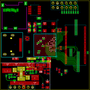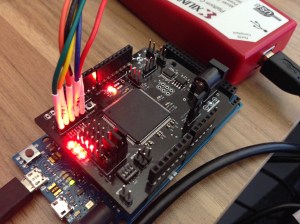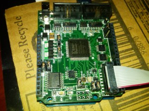
[Kodera2t] wanted to experiment with programmable logic. Instead of going with an FPGA board, he decided to build his own CPLD (complex programmable logic device) board, with a built-in programmer. The CPLD is a Xilinx 9536 which is inexpensive and, though obsolete, still readily available. The programmer for the board uses an FT232RL and the total cost is very low ([kodera2t] says it is in the price range of a Raspberry Pi Zero or about $4).
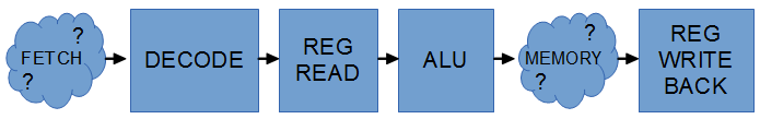
From a user’s point of view, a CPLD is just a small FPGA. Internally, there is a significant difference in how they implement your design. Although there are differences between different product families, CPLDs usually use a sea of logic gates arranged as an AND/OR chain. By feeding inputs and inverted inputs into the AND gates and then ORing the results, you can build interesting logic circuits. However, modern CPLDs use Verilog or VHDL, so you describe what you want just like with an FPGA and the software figures out how to use the underlying circuits to give you what you want.