The sun may be spotless, but that doesn’t mean it isn’t doing interesting things. A geomagnetic storm is predicted for this weekend, potentially giving those at latitudes where the Northern Lights are not common a chance to see a cosmic light show. According to SpaceWeather.com, a coronal hole, a gap in the sun’s atmosphere that can let the solar wind escape, is about to line up with Earth. The last time this hole was on the Earth-facing side of the sun, the resultant storm gave aurora as far south as Colorado. So if you’re in any of the northern tier states, you might want to find somewhere with dark skies and a good view to the north this weekend.
It’s not only space weather that’s in the news, but weather-weather too. Hurricane Dorian will probably make landfall as a Category 4 storm, probably along Florida’s Atlantic coast, and probably in the middle of the night on Monday. That’s a lot of uncertainty, but one thing’s for sure: amateur radio operators will be getting into the action. The Hurricane Watch Net will activate their net for Dorian on Saturday afternoon at 5:00 PM Eastern time, ready to take reports from stations in the affected area. Not a ham? You can still listen to the live feed once the net activates.
Hams aren’t the only ones getting geared up for Dorian, though. Weather satellite enthusiasts are pointing their SDRs at the sky and grabbing some terrifyingly beautiful pictures of Dorian as it winds up. Some of the downloaded images are spectacular, and if you’ve got an SDR dongle and a couple of pieces of coat hanger wire, you too can spy on Dorian from any number of satellites.
Speaking of which, over on r/RTLSDR, someone has done a little data mining and shown that NOAA 15 is still very much alive. u/amdorj plotted the scan motor current draw and found that it steadily decreased over time, possibly indicating that the bearings aren’t as worn as previously thought. We recently covered the story of the plucky satellite that’s almost two decades past its best-by date; here’s hoping our report on its death was greatly exaggerated.
In one of the weirder bits of marketing we’ve seen lately, NASA decided to name a rock on Mars after septuagenarian rockers The Rolling Stones. The golf ball size rock was blasted about a meter across the Martian landscape when the Mars InSight lander touched down in 2018, leaving a small scar in the dust. The stone had obviously rolled, so phone calls were made and one thing led to another, and before you know it, Robert Downey Jr. is making the announcement before a Stones concert at the Rose Bowl, right in JPL’s backyard. There’s even a cute animation to go along with it. It’s a nice piece of marketing, but it’s not the first time the Stones have been somewhat awkwardly linked to the technology world. We dare you not to cringe.
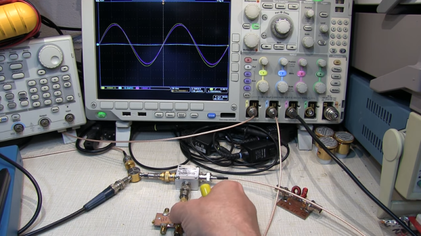
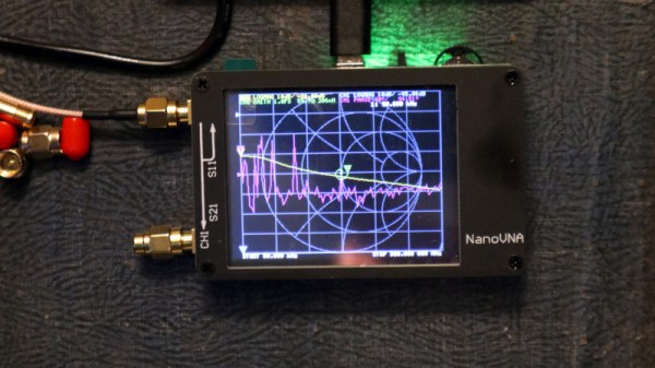
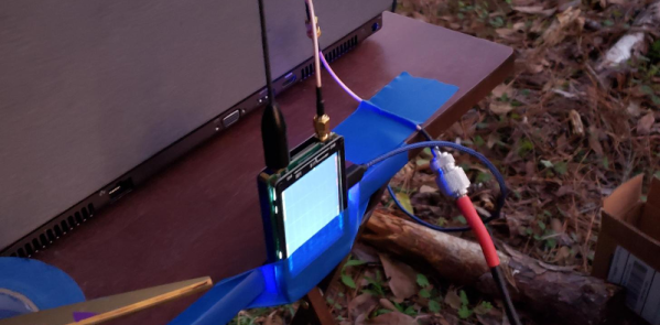
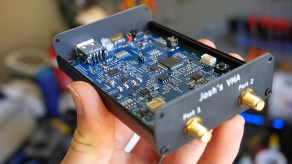
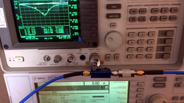
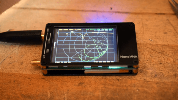
We’ll finish up today with something not related to space. As Al Williams recently covered, for about fifty bucks you can now score a vector network analyzer (VNA) that will do all sorts of neat RF tricks. The NanoVNA sounds like a great buy for anyone doing RF work, but its low price point and open-source nature mean people are finding all kinds of nifty uses for it. One is measuring the length of coax cables with time-domain reflectometry, or TDR. Phasing antenna arrays? the NanoVNA sounds like the perfect tool for the job.