Building Touch Sensors From Digital Barometer Chips

A couple of Harvard researchers have developed a method of using digital barometers as a touch sensor. The good news for us is that they’ve open sourced the project, including Eagle board files, firmware, and details about the materials they used.

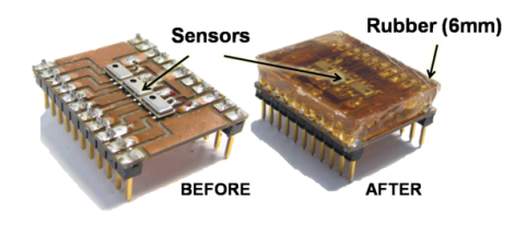
The digital barometers were chosen for their characteristics, availability, and low-cost. The sensor uses an array of Freescale MPL115A2 chips, a MEMS Barometer designed for use in altimeters. The mass production makes them cheap (Octopart found some in single quantities for $1.71 at the time of writing). The chips are soldered onto a board which is then cast in rubber. This distributes the force while protecting the sensors. The video after the break shows them standing up to rubber hammer blows and supporting a 25 pound weight.

There are a few tricks to reading the array. The first is that the devices are designed to be used one-to-a-project so they have a fixed i2 address. A separate chip must be used to address them individually. But one it’s up and running you should be able to use it as feedback for the fingertips of that robot arm you’ve been building.

Continue reading “Building Touch Sensors From Digital Barometer Chips”

PlayStation Gaming On A NOOK Simple Touch

Improvements in processing power really hit home when you see an eBook reader playing PlayStation games. Sure, we’re talking about a system which launched more than 15 years ago (the original PlayStation launched way back in 1995), but this is a $99 device which seems to be playing the games at full speed!

[Sean] wrote in to share the project with us. After rooting the device he installed System 7 (aka Mac OS 7) using Mini vMac for Android. He uses Free PlayStation Emulator (FPSE) to run the games. There is an Android version which provides the touch-screen controls you see above. We figured the graphics would be awful, but the video after the break proves us wrong. Other than being in black and white we think the graphics are fantastic. Just one hack was necessary to make this happen. [Sean] uses NoRefresh to keep the Nook from refreshing the screen which is what causes the film-negative type of flashing after several page turns.

Continue reading “PlayStation Gaming On A NOOK Simple Touch”

Can A Kickstarter Project Actually Build A Space Elevator?

It’s the stuff that Science Fiction is made of: an elevator that climbs its way into space rather than needing a rocket to get there. Can it be done? No. But this Kickstarter project aims to fund research that will eventually make a space elevator possible. They’re already way over their goal, and plan to use the extra funds to extend the reach of the experiments.

A complete success would be a tether that reaches into space, held taught by a weight which is pulled away from earth by centrifugal force. That’s not really on the radar yet (last we heard humans weren’t capable of producing a substance strong enough to keep the tether from snapping). What is in the works is a weather balloon supporting a ribbon which a robot can climb. The team isn’t new to this, having built and tested several models at University and then in a start-up company that closed its doors a few years ago. Now they’re hoping to get a 3-5 kilometer ribbon in the air and to build a new robot to climb it.

For now we’ll have to be satisfied with the 1000 ft. climb video after the break. But we hope to see an Earth-Moon freight system like the one shown in the diagram above before the end of our lifetimes.

Continue reading “Can A Kickstarter Project Actually Build A Space Elevator?”

Portable Radio Station Gets A Beautiful Case

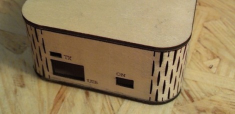
[Martin] put together a simple portable radio unit to take some MP3s with him while he’s out and around. The build was simple; just a no-name Chinese MP3 player, a battery, and an FM radio transmitter. To give his project a little more pizzazz, he came up with a very handsome laser cut wooden case to turn what would be a bunch of wires and components into an attractive build.

[Martin]’s case makes wonderful use of the kerf bending technique. By cutting small staggered lines in a piece of plywood, [Martin] was able to bend his laser cut enclosure into a surprisingly tight radius. With the help of a pair of laser cut forms and a bit of hot water and glue, he was able to make the shape of his case permanent.

The top and bottom of his case are also laser cut plywood, but [Martin] included a translucent plexiglas logo on the top. When his radio unit is activated a LED inside his project box lights up, illuminating his personal logo.

Kerf bending is something we’ve seen before, and we’re looking forward to seeing more project boxes use it in the future, hopefully with the application of a veneer to cover the diamond-shaped holes.

AVR Fuse Bits Explained

Every AVR microcontroller, from the ATtiny in your thermostat to the ATMega in your Arduino, stores its configuration in a series of fuse bits. These fuse bits control settings such as the multiplier of the internal oscillator (and thus the speed of the chip), or if the reset pin can be used as a GPIO pin. [YS] just put up an awesome tutorial for understanding these fuse/lock bits, and it’s just the reference guide you’ll need when you find your AVR is running 8 times slower than you would like.

As an example, [YS] uses the ATMega48 default settings. From the factory, the ‘Mega48 ships with it’s fuse bits set to use an 8MHz internal RC oscillator with the CKDIV8 bit set. This results in the chip operating at 1MHz, a bit slow for [YS]’ liking.

By looking at the datasheet for the ATMega48, [YS] found the CKDIV8 fuse was the 7th bit in the low fuse byte. From the factory, the default value for this byte is 0b01100010. To remove the ‘divide clock by 8’ bit, [YS] needed to change the low byte to 0b11100010, or 0xE2. This is done via AVRdude by appending lfuse:w:0xE2:m to the commands entered when programming.

Fuse bits don’t need to be scary. As long as you can convert between binary and hex, can remember there are 7 bits in a byte (remember to start counting from 0), and have access to an easy to use fuse calculator, it’s possible to change all the settings on any AVR you have on hand.


Rebuilding The Electronics In A Remote Control Car

Inspired by the many autonomous rovers such as Curiosity and the self-driving Google car, [Rohit] decided to build his own by taking an off-the-shelf remote control car and adding his own electronics. Unfortunately, he couldn’t find the datasheet for the chip used to receive radio signals and drive the motors, so he ended up building his own electronics and putting them in the car.

[Rohit]’s car – the Thunder Rumbler RC Car – is driven by applying power to two motors. This is an easy system to control, as only two channels are needed to make the car go forward, left, right, or backwards. To drive these two motors, [Rohit] found an SN754410 quadruple half-H bridge driver chip lying in his box of assorted electronic components. Thanks to a helpful instructable, this chip was easily controlled with an Arduino.

That left the problem of sending a wireless signal to the Arduino. [Rohit] accomplished this by relying on an Android phone to provide the remote control.

[Rohit] whipped up a small program running on his desktop that allows him to send ‘L’, ‘R’, ‘U’, or ‘D’ to the Android phone to dictate if the car should go left, right, forward, or reverse. The Android phone receives these commands via the Internet and sends an audio signal through the headphone port. This audio signal is connected to two analog pins of the Arduino. With a little bit of software and a bit of reading up on frequency shift keying, [Rohit] was able to make his car move in any direction.

Even though [Rohit] realized his goal of controlling a remote control car on his own terms, the build is far from done. He plans on adding some ultrasonic sensors and using the Android’s camera for object detection.

Building A Driver For Absurdly High Power LEDs

A few years ago, the highest power LEDs you could buy capped out around three watts. Now, LED manufacturers are taking things to ridiculous power ratings with 30, 40, and even 90 watt LEDs. Getting these high-power LEDs are no longer a problem, but powering them certainly is. [Thomas] built a LED driver capable of powering these gigantic LEDs and creating a light show that is probably bright enough to cause bit of eye damage.

[Thomas]’ LED driver is based on Linear Technology’s LT3518 LED driver. This driver is part of a project to build a huge WiFi controlled RGB LED, so the driver has outputs for three separate LEDs capable of sourcing 700 mA each.

Because [Thomas] is dealing with crazy amounts of heat and power required to light up these huge LEDs, the driver board features a temperature sensor next to each LED driver. When the board gets too hot, the driver automatically shuts down, preventing bad things from happening.

You can check out a few pictures of [Thomas]’ LED driver over on the build page for his WiFi LED project. A truly awesome amount of lighting power here, that also makes it impossible to get a good picture of the board in operation.