One Dollar USB Sound Card Turned O-Scope

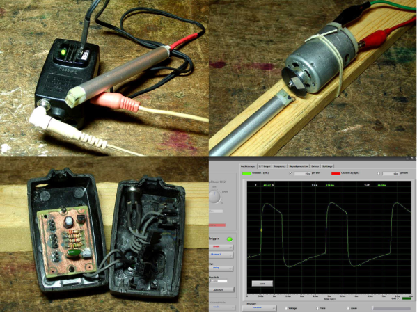
Using the inputs on a computer’s sound card is an old trick to fake a very simplistic, AC coupled, slow oscilloscope. You can get DC operation by desoldering a couple capacitors, but if the sound card is integrated into the motherboard it raises the stakes if you mess that up.

[TMSZ] has a better option, a ~1 dollar USB sound card which is easily hacked to work as a simple oscilloscope. Easily found on eBay, the 7.1 virtual channel sound card is identical in brains to a more expensive c-media model, but the layout of the PCB makes it easier to bypass the DC blocking caps. Software and DLL files to use the sound card with Miniscope v4 — a Windows GUI for oscilloscopes — are also linked, so getting set up should be fairly simple.

Now of course this is not lab-grade measurement equipment: the sampling rate is limited to 44KHz and the voltages must be in the typical “line level” range, under two volts. If you don’t mind a little extra noise, you can increase the input impedance with a single resistor. This extends the input range up to six volts, which covers most hobby and microcontroller usage.

So if you’re really in need of a scope, but only have a buck to spend, this may be just the hack for you! Those willing to shell out a hefty sum for a high-end headless oscilloscope should look onto the virtual bench.

Sound Card Tachometer Rises From The Junkbox

We love writing up projects that re-use lots of old parts. In fact, we save the links and use them as defense when our significant other complains about the “junk” in the basement. No, that tactic hasn’t ever worked, but we’re going to keep trying. Case in point, [Wotboa] needed a non-contact tachometer. There are plenty of commercial products which do just that. After consulting his parts bin, [wotboa] realized he had everything he needed to hack out his own. An IR break beam sensor from an old printer was a perfect fit in an aluminum tube. With the outer shell removed, the emitter and detector were mounted in the nylon shell of an old PC power supply connector, effectively turning them pair into a reflective sensor. To amplify the circuit, [wotboa] used a simple 2n2222 transistor circuit. The key is to keep the voltage seen by the sound card the range of a line level signal. This was accomplished by adding a 2.2 Megohm resistor in line with the output. [wotboa] drew his schematic in eagle, and etched his own PCB for the project. Even the tachometer’s case came from the parts bin. An old wall wart power supply gave up its shell for the cause, though [wotboa] is saving the transformer for another project.

For sensing, [wotba] used [Christian Zeitnitz’s] Soundcard Oscilloscope software.  Measuring the RPM of the device under test is simply a matter of determining the frequency of the signal and multiplying by 60. A 400 Hz signal would correspond to a shaft turning at 24,000 RPM. The circuit performs well in the range of RPM [wotboa] needs, but using a sound card does have its limits. The signals on the scope look a bit distorted from the square waves one would expect. This is due to the AC coupled nature of sound cards. As the signal approaches DC, the waveform will become more distorted. One possible fix for this would be to remove the AC coupling capacitor on the sound card’s input. With the capacitor removed, an op amp buffer would be a good idea to prevent damage to the sound card.

[Via Instructables]

From Reference Design To USB Sound Card

[Entropia] decided to try his hand at rolling is own sound card. He picked out a DAC chip, started his prototyping by studying the reference design from the datasheet, then went through several iterations to arrive at this working model.

He chose to base the board around the PCM2706. It’s a digital to analog converter that has built-in USB support; perfect for his needs. It’s got a headphone amplifier, but is also capable of putting out S/PDIF signals for a digital amplifier to pick up and use. Not bad for a part that can be had for right around eight bucks.

The first PCB he designed had a few electrical and footprint errors. But he was able to get it to run by adding some point-to-point jumpers, and bending the legs of his capacitors to fit the board area. With those issued accounted for he ordered a second batch of boards. These went together nicely, but the headphone output was incredibly loud. Turns out the filtering circuit had the wrong resistor and capacitor values. Changing them around, and swapping the audio output so that the correct channels were patched to the audio jack brings it to the first release version seen above.

Program An Arduino Using Your Sound Card

audioino_programming_arduino_with_sound

[Chris] wrote us to share a neat technique he has been using to program the Arduinos he uses in his projects. He likes to build bare bones Arduino clones rather than sacrifice full dev boards, and instead of programming them via traditional means, he is using his computer’s sound card.

He builds a simple dead bug Arduino (which he calls an Audioino) using a handful of resistors, a pair of caps, an LED, a reset switch, and most importantly – an audio jack. After burning a special audio bootloader to the chip, he can connect the Arduino directly into his computer’s speaker port for programming.

Once the microcontroller is connected to his computer, he runs the IDE-generated hex file through a Java app he created, which converts the data into a WAV file. With the Arduino put into programming mode, he simply plays the WAV file with an audio player, and the code is uploaded.

He says that this method of programming comes in handy in certain cases where he builds things for friends, because they can easily update the software on their own without a lot of fuss.

Sound Card Microcontroller/PC Communication

The usual way send data from a microcontroller is either over RS-232 with MAX232 serial ICs, crystals, and a relatively ancient computer, or by bit-banging the USB protocol and worrying about driver issues. Not content with these solutions, [Scott] came up with sound card μC/PC communication that doesn’t require any extra components.

[Scott] bought a cheap USB sound card dongle on eBay (although a built-in sound card will do) and wired up the tip and ring of the plug to the microcontroller. The data is sent from the microcontroller a lot like Morse code – a short gap between pulses is a zero, a long gap is a one. This is parsed by a Python script using PyAudio. Synchronization, timing, and calibration is automatic because of a 10-bit ‘packet header’ explained in this video.

Continue reading “Sound Card Microcontroller/PC Communication”

Sound Card Driven Servo Motor

[youtube=http://www.youtube.com/watch?v=1LG2Ecsk13Q]

[Darrell] is using a sound card to drive this servo motor. The motor draws power from a cellphone battery with the control signal coming from one of the audio channels. It’s not too surprising that this works since the motor just needs a PWM signal to operate and that’s what is used to create the different frequencies of sound on electronic speakers. We’re not sure what [Darrell’s] got planned for this system but he mentions that two servos can be used, one on each audio channel. If you’re not using your sound card this would be a way to stop using the Arduino for that mail checker and just use a little flag attached to a servo. When mail comes in the appropriately engineered sound raises the flag.

Make An ECG With Your Sound Card


[Marcus] sent in his work on making ECGs. His first one was inspired by [Jason]’s. Believe it or not, you can build this thing for under $5. After getting it semi-functional, he decided to pick up a cheap one and mod it for PC input via the sound card. (There are plenty of sound card oscilloscope projects that will work for this.) Remember kids, don’t go sticking electrodes on anyone unless you know what you’re doing: correctly placed electrical shocks (even low power ones) can be deadly.