Need A Low-Mass Antenna In Space? Just Blow It Up!

A parabolic antenna is a simple enough device, a curved reflector designed to focus all the radiation from the direction it’s pointed into a waveguide or antenna at its feedpoint. They’re easy enough to make for a radio amateur, but imagine making one for a spacecraft. It must fold into a minimal space and weigh almost nothing, both difficult to achieve. An engineering academic doing work for NASA, [Christopher Walker], has a new way to make the parabolic surface that solves the spacecraft designer’s problems at a stroke, it forms its parabolic reflector on the inside of an inflatable structure. In this way relatively huge reflectors can be built in space, with easy folding and very little weight. Continue reading “Need A Low-Mass Antenna In Space? Just Blow It Up!”

Better Antennas Via Annealing (Simulated)

If you want to simulate a tic-tac-toe game, that’s easy. You can evaluate every possible move in a reasonable amount of time. Simulating antennas, however, is much harder. [Rosrislav] has been experimenting with using simulated annealing to iterate antenna designs, and he shares his progress in a recent blog post.

For many problems, it simply isn’t possible to try all possible inputs to determine what provides the “best” result. Instead of trying every single input or set of inputs, you can try random ones and discard all but the best guesses. Then you make small changes and try again. The only problem is that the algorithm may lock in on a “local maximum” — that is, a relatively high value that isn’t the highest because it forms a peak that isn’t the highest peak. Or, if you are looking for a minimum, you may lock on to a local minimum — same thing.

To combat that, simulated annealing works like annealing a metal. The simulation employs a temperature that cools over time. The higher the temperature, the more likely large changes to the input are to occur.

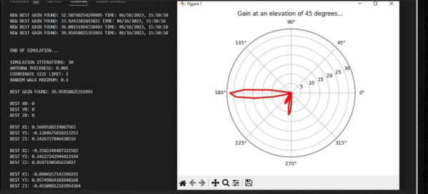
The Python program uses the PyNEC package to provide simulation. The program sets up random antenna lengths and finds the projected gain, attempting to optimize for maximum gain.

The post is long on code and short on details, so you will probably want to read the Python source to see exactly what it is doing. But it could probably serve as a template to do other simulated annealing simulations for other antennas or anything you had a simulation engine to evaluate.

Several techniques allow you to optimize things that are too hard to search exhaustively, and we’ve talked about simulated annealing and genetic algorithms before. However, lately, we’ve been more interested in annealing 3D prints.

3D Printing Antennas With Dielectric Resin

[Machining and Microwaves] has long wanted to use a 3D printer to print RF components for antennas and microwave lenses. He heard that Rogers — the company known for making PCB substrates, among other things — had a dielectric resin available and asked them if he could try some. They agreed, with some stipulations, including that he had to visit their facility and show his designs in a video. Because of that, the video seems a little bit like a commercial, but we think he is genuinely excited about the possibility of the resin.

Since he was in their facility, he was able to interview several of the people behind the resin, and they had some interesting observations about keeping resin consistent during printing and how the moonbounce feed he wanted to print would work.

Some of the exotic RF test equipment was interesting to see, too. The microwave lenses look like some kind of modern art. According to the Roger’s website:

Radix Printable Dielectric materials are a ceramic-filled, UV-curable polymer designed for use with photopolymer 3D-printing processes like sterolithography (SLA) and digital light processing (DLP) printing. These materials and printing processes enable the use of high-resolution, scalable 3D-printing for complex RF dielectric components such as gradient index (GRIN) lenses or three-dimensional circuits. The 2.8Dk printable dielectric is designed to have low loss characteristics through millimeter wave (mmWave) frequencies and low moisture absorption for end-use applications.

It isn’t clear to us that you could use this resin in your own printers, but they did look pretty similar to what we have hanging around except, perhaps, for the continuous circulation of the resin pool. We figured the resin wasn’t inexpensive. In fact, we found a liter online for $1,863. We don’t know if that’s the suggested retail price or not, but we also suppose if you need this material, you won’t be that surprised at the cost.

If you don’t need microwave frequencies, you might be able to get by with some easier techniques. Or, you can even do something slightly more difficult but probably a lot cheaper.

Continue reading “3D Printing Antennas With Dielectric Resin”

Identify That Antenna By Sight

It’s a skill that radio amateurs pick up over years but which it sometimes comes as a surprise to find that is not shared by everyone, the ability to casually glance at an antenna on a mast or a rooftop and guess what it might be used for. By which of course I mean not some intuitive ability to mentally decode radio signals from thin air, but most of us can look at a given antenna and immediately glean a lot of information about its frequency and performance. Is this privileged knowledge handed down from the Elmers at the secret ceremony of conferring a radio amateur’s licence upon a baby ham? Not at all, in fact stick around, and I’ll share some of the tricks. Continue reading “Identify That Antenna By Sight”

A close-up view of surface-mount components on a circuit board

Smaller Is Sometimes Better: Why Electronic Components Are So Tiny

Perhaps the second most famous law in electronics after Ohm’s law is Moore’s law: the number of transistors that can be made on an integrated circuit doubles every two years or so. Since the physical size of chips remains roughly the same, this implies that the individual transistors become smaller over time. We’ve come to expect new generations of chips with a smaller feature size to come along at a regular pace, but what exactly is the point of making things smaller? And does smaller always mean better?

Smaller Size Means Better Performance

Over the past century, electronic engineering has improved massively. In the 1920s, a state-of-the-art AM radio contained several vacuum tubes, a few enormous inductors, capacitors and resistors, several dozen meters of wire to act as an antenna, and a big bank of batteries to power the whole thing. Today, you can listen to a dozen music streaming services on a device that fits in your pocket and can do a gazillion more things. But miniaturization is not just done for ease of carrying: it is absolutely necessary to achieve the performance we’ve come to expect of our devices today. Continue reading “Smaller Is Sometimes Better: Why Electronic Components Are So Tiny”

What Makes A Good Antenna?

It sometimes seems as though antennas and RF design are portrayed as something of a Black Art, the exclusive preserve of an initiated group of RF mystics and beyond the reach of mere mortals. In fact though they have their difficult moments it’s possible to gain an understanding of the topic, and making that start is the subject of a video from [Andreas Spiess]. Entitled “How To Build A Good Antenna”, it uses the design and set-up of a simple quarter-wave groundplane antenna as a handle to introduce the viewer to the key topics.

What makes this video a good one is its focus on the practical rather than the theoretical. We get advice on connectors and antenna materials, and we’re introduced to the maths through online calculators rather than extensive formulae. Of course the full calculations are there to be learned by those with an interest, but for many constructors they can be somewhat daunting. We’re shown a NanoVNA as a useful tool in the antenna builder’s arsenal, one which gives a revolutionary window on performance compared to the trial-and-error of previous times. Even the ground plane gets the treatment, with its effect on impedance and gain explored and the emergence of its angle as a crucial factor in performance. We think this approach does an effective job of breaking the mystique surrounding antennas, and we hope it will encourage viewers to experiment further.

If your appetite has been whetted, how about taking a look at a Nano VNA in action?

Continue reading “What Makes A Good Antenna?”

Tracking Satellites: The Nitty Gritty Details

If you want to listen to satellites, you have to be able to track them as they pass over the sky. When I first started tracking amateur satellites, computing the satellite’s location in the sky was a part of the challenge. Nowadays, that’s trivial. What’s left over are all the extremely important real-world details.  Let’s take a look at a typical ham satellite tracking setup and see how it all ties together.

Rotators for Steering

The popularity of robotics, 3D printing, and CNC machines has resulted in a deluge of affordable electric motors and drivers. It’s hard to imagine that an electric motor for rotating an antenna would be anything special, but in fact, antenna rotators are non-trivial engineering designs. Most of the challenges are mechanical, not electrical — the antennas that they drive can be huge, have significant wind loading and rotational inertial, and just downright weigh a lot. A rotator design has to consider bearings, weather exposure, all kinds of loads, not just rotational. And usually a brake is required to keep the antenna pointed in windy conditions.

There’s been a 70-some year history of these mechanisms from back in the 1950s when Cornell Dubilier Electronics, the company you know as a capcacitor manufacturer, began making these rotators for television antennas in the 1950s. I was a little surprised to see that the rotator systems you can buy today are not very different from the ones we used in the 1980s, other than improved electronic controls. Continue reading “Tracking Satellites: The Nitty Gritty Details”