A DIY Electronic Load With A Twist

If you’re testing a power supply or battery pack, an electronic load is a nice tool to have. By watching the voltage as you crank up the resistance, you can verify the unit’s real-world capabilities quickly and easily. But [Xavier Bourlot] wanted a bit more information than is generally afforded by these devices, so he came up with his own scratch built load that can measure the voltage at multiple points in the circuit.

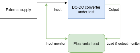
Now at first glance, it might not be obvious why you’d want such a capability. But [Xavier] is looking to do something very specific with this device: analyze the efficiency of DC-DC converters. The idea is that if the electronic load can measure the voltage on both sides of the converter, it can calculate what kind of losses are being incurred.

Could you do this with a multimeter and a traditional electronic load? Sure. But if it’s the kind of thing you’ll be doing a lot of, it’s not hard to see why this method would be preferable.

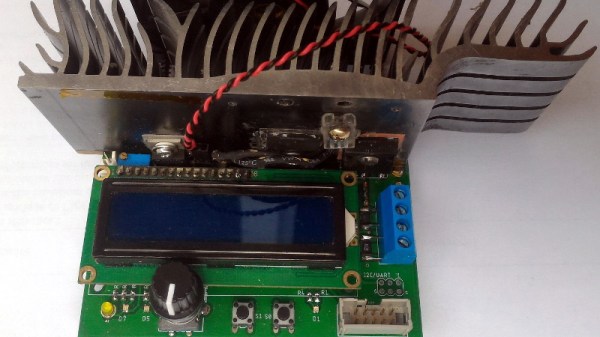
But even if you ignore the converter analysis capabilities, this looks to be a very useful device to have around the lab. [Xavier] says it can sink more than 5 amps, and handle an input voltage as high as 100 volts. Powered by an ATmega328P, the load is also fully programmable and even features an I2C expansion port that you can use to hang additional hardware or sensors on. The stock firmware is already quite capable, and the list of future enhancements has some very interesting entries such as the ability to log data over serial or to a SD card.

We’ve seen a number of programmable electronic load projects over the years, ranging from Arduino shields to VFD equipped units that would be the pride of any hacker’s bench.

Tesla Model 3 Battery Pack Teardown

The Tesla Model 3 has been available for almost a year now, and hackers and tinkerers all over the world are eager to dig into Elon’s latest ride to see what makes it tick. But while it’s considerably cheaper than the Model S that came before it, the $35,000+ USD price tag on the new Tesla is still a bit too high to buy one just to take it apart. So for budget conscious grease monkeys, the only thing to do is wait until somebody with more money than you crashes one and then buy the wreckage cheaply.

Tesla Model 3 battery monitor board

Which is exactly what electric vehicle connoisseur [Jack Rickard] did. He bought the first wrecked Model 3 he could get his hands on, and proceeded to do a lengthy teardown on what’s arguably the heart and soul of the machine: its 75 kWh battery pack. Along the way he made some interesting discoveries, and gained some insight on to how Tesla has been able to drop the cost of the Model 3 so low compared to their previous vehicles.

On a Tesla, the battery pack is a large flat panel which takes up effectively the entire underside of the vehicle. To remove it, [Jack] and his assistant raise the wreck of the Model 3 up on a standard lift and then drop the battery down with a small lift table. Here the first differences are observed: while the Model S battery was made for rapid swapping (a feature apparently rarely utilized in practice), the battery in the Model 3 battery is obviously intended to be a permanent piece of the car; removing it required taking out a good portion of the interior.

With the battery out of the car and opened up, the biggest change for the Model 3 becomes apparent. The battery pack actually contains the charger, DC-DC converter, and battery management system in one integrated unit. Whereas on the Model S these components were installed in the vehicle itself, on the Model 3, most of the primary electronics are stored in this single module.

That greatly reduces the wiring and complexity of the car, and [Jack] mentions the only significant hardware left inside the Model 3 (beyond the motors) would be the user interface computer in the dashboard. When the communication protocol for this electronics module is reverse engineered, it may end up being exceptionally useful for not only electric vehicle conversions but things like off-grid energy storage.

A little over a year ago we featured a similar teardown for the battery back in the Tesla Model S, as well as the incredible project that built a working car from multiple wrecks.

[Thanks to DarksideDave for the tip.]

Continue reading “Tesla Model 3 Battery Pack Teardown”

Fail Of The Week: NASA Edition

There’s a reason we often use the phrase “It ain’t Rocket Science”. Because real rocket science IS difficult. It is dangerous and complicated, and a lot of things can and do go wrong, often with disastrous consequences. It is imperative that the lessons learned from past failures must be documented and disseminated to prevent future mishaps. This is much easier said than done. There’s a large number of agencies and laboratories working on multiple projects over long periods of time. Which is why NASA has set up NASA Lessons Learned — a central, online database of issues documented by contributors from within NASA as well as other organizations.

The system is managed by a steering committee consisting of members from all NASA centers. Public access is limited to a summary of the original driving event, lessons learned and recommendations. But even this information can be quite useful for common folks. For example, this lesson on Guidance for NASA Selection & Application of DC-DC Converters contains several bits of useful wisdom. Or this one about IC’s being damaged due to capacitor residual discharge during assembly. If you ever need to add a conformal coating to your hardware, check how Glass Cased Components Fractured as a Result of Shrinkage in Coating/Bonding Materials Applied in Excessive Amounts. Finally, something we have all experienced when working with polarized components — Reverse Polarity Concerns With Tantalum Capacitors. Here is a more specific Technical Note on polarized capacitors (pdf): Preventing Incorrect Installation of Polarized Capacitors.

Unfortunately, all of this body of past knowledge is sometimes still not enough to prevent problems. Case in point is a recently discovered issue on the ISS — a completely avoidable power supply mistake. Science payloads attach to the ISS via holders called the ExPRESS logistics carriers. These provide mechanical anchoring, electrical power and data links. Inside the carriers, the power supply meant to supply 28V to the payloads was found to have a few capacitors mounted the other way around. This has forced the payloads to use the 120V supply instead, requiring them to have an additional 120V to 28V converter retrofit. This means modifying the existing hardware and factoring in additional weight, volume, heat, cost and other issues when adding the extra converter. If you’d like to dig into the details, check out this article about NASA’s power supply fail.

Thanks to [Jarek] for tipping us about this.

Christmas Star Uses Two AA Batteries

When [hkdcsf] was a teenager, he made a Christmas star with an up counter driving decoder logic and using transistors to light LEDs in festive patterns. He’s revisited this project using modern techniques including a microcontroller, a DC/DC converter, and constant current LED drivers.

The project uses two AA batteries, and that’s what makes the DC/DC converter necessary. Blue LEDs have a forward voltage of just over 3V, and the LED driver chip requires about 0.6V of overhead. Two fresh AAs will run a tad above 3V, but as they discharge, or if he’s using rechargeables, there just won’t be enough potential. To make sure the star works even with whatever LEDs are chosen, the converter takes the nominal 3V from the batteries and converts it to 3.71V.

Continue reading “Christmas Star Uses Two AA Batteries”

The USB Killer, Version 2.0

There are a lot of stupid things you can do with the ports on your computer. The best example is the Etherkiller, an RJ45 plug wired directly to a mains cable. Do not plug that into a router. USB is a little trickier, but with a sufficient number of caps, anyone can build a USB killer that will fry any computer (.ru, Google Translatrix)

The USB Killer v2.0 is [Dark Purple]’s second version of this device. The first version was just a small board with a DC/DC converter, a few caps, and a FET. When plugged in to a computer, the converter would charge the caps up to -110V, dump that voltage into the USB signal wires, and repeat the entire process until the computer died. This second version is slightly more refined, and it now dumps -220V directly onto the USB signal wires. Don’t try this at home.

So, does the device work? Most definitely. A poor Thinkpad X60 was destroyed with the USB killer for purposes of demonstration in the video below. This laptop was originally purchased just for the test, but the monster who created the USB killer grew attached to this neat little laptop. There’s a new motherboard on the way, and this laptop will live again.

Continue reading “The USB Killer, Version 2.0”