DIY Vacuum Table Enhances PCB Milling

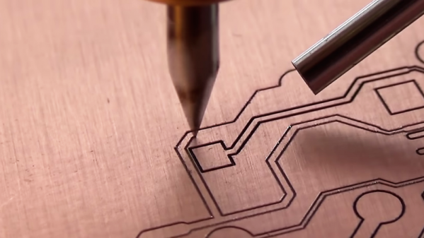
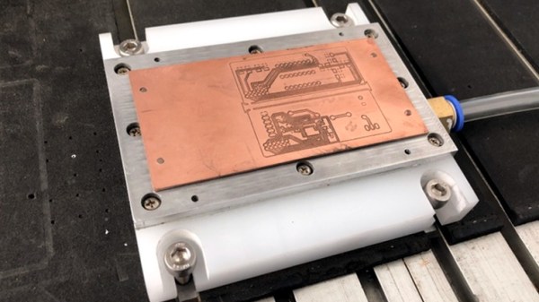
CNC milling a copper-clad board is an effective way to create a PCB by cutting away copper to form traces instead of etching it away chemically, and [loska] has improved that process further with hisĀ DIY PCB vacuum table. The small unit will accommodate a 100 x 80 mm board size, which was not chosen by accident. That’s the maximum board size that the free version of Eagle CAD will process.

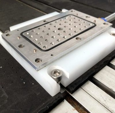
When it comes to milling PCBs, double-sided tape or toe clamps are easy solutions to holding down a board, but [loska]’s unit has purpose behind its added features. The rigid aluminum base and vacuum help ensure the board is pulled completely flat and held secure without any need for external fasteners or adhesives. It’s even liquid-proof, should cutting fluid be used during the process. Also, the four raised pegs provide a way to reliably make double-sided PCBs. By using a blank with holes to match the pegs, the board’s position can be precisely controlled, ensuring that the back side of the board is cut to match the front. Holes if required are drilled in a separate process by using a thin wasteboard.

Milling copper-clad boards is becoming more accessible every year; if you’re intrigued by the idea our own [Adil Malik] provided an excellent walkthrough of the workflow and requirements for milling instead of etching.

CNC Machine Most Satisfyingly Mills Double-Sided PCBs

We know that by this point in the development of CNC technology, nothing should amaze us. We’ve seen CNC machines perform feats of precision that shouldn’t be possible, whether it be milling a complex jet engine turbine blade or just squirting out hot plastic. But you’ve just got to watch this PCB milling CNC machine go through its paces!

The machine is from an outfit called WEGSTR, based in the Czech Republic. While it appears to be optimized for PCB milling and drilling, the company also shows it milling metals, wood, plastic, and even glass. The first video below shows the machine milling 0.1 mm traces in FR4; the scale of the operation only becomes apparent when a gigantic toothbrush enters the frame to clear away a little swarf. As if that weren’t enough, the machine then cuts traces on the other side of the board; vias created by filling drilled holes with copper rivets and peening them over with a mandrel and a few light hammer taps connect the two sides.

Prefer your boards with solder resist and silkscreening? Not a problem, at least judging by the second video, which shows a finished board getting coated with UV-cure resist and then having the machine mill away just the resist on the solder pads. We’re not sure how they deal with variations in board thickness or warping, but they sure have it dialed in. Regardless of how they optimized the process, it’s a pleasure to watch.

At about $2,600, these are not cheap machines, but they may make sense for someone needing high-quality boards with rapid turnaround. And who’s to say a DIY machine couldn’t do as good a job? We’ve seen plenty of them before, and covered the pros and cons of etching versus milling too.

Continue reading “CNC Machine Most Satisfyingly Mills Double-Sided PCBs”

Laser Cutter Helps Make Dual Sided PCBs

laser-cutter-dual-sided-pcb

[Rich Olson] wrote in to share his technique for making dual-sided printed circuit boards using a laser cutter. Unfortunately this still depends on etching copper clad boards with chemicals. But his process makes it really easy to produce well-defined and precisely aligned etch resist on both sides of the board all at once.

This can be really tough to do with the toner transfer method. The most common way would be to use a light box to align the two printouts of resist, taping them together before putting the copper clad in between and sending the whole thing though a laminator. [Rich] uses a scrap of acrylic to ensure alignment. He tapes it to the bed of his Epilog laser cutter and cuts the board outline out (that’s the void you see in the image). He removes the scrap and uses it as a stencil for cutting out the copper clad. After prepping the board he coats both sides and sends it through the laser cutter to burn away the paint where he wants to remove copper. Don’t miss his video embedded after the break.

The acrylic outline trick is similar to the laser cutter fence we heard about several weeks back.

Continue reading “Laser Cutter Helps Make Dual Sided PCBs”

Spinning POV Clock Done Oh-so-right

[Kizo] builtĀ an extraordinary persistence of vision clock. The design uses a PC cooling fan to spin the propeller-like PCB. As it goes around, a hall effect sensor synchronizes the illumination of the LEDs to draw the display. Power for the rotating electronics is transferred wirelessly via a transformer on the base and coil on the spinning board. The final version uses an ATmega324 microcontroller running at 20 MHz and has an IR receiver for changing the settings. The 3000 lines of code bring a lot of bells and whistles, including a menu system with a huge amount of settings from tweaking the clock display, to font selection for scrolling messages. Take a look at the demo after the break. The double-sided board looks like it’s pretty difficult to etch at home, but as you can see from the forum post (translated), [Kizo] did a great job on this build from start to finish. Continue reading “Spinning POV Clock Done Oh-so-right”