Spin Up To Speed With This Stroboscope

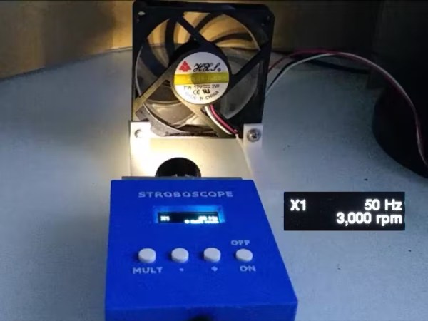
A stroboscope is not the most common tool, and while they can be purchased fairly inexpensively from various online stores, they are straightforward enough tools that plenty of us could build our own mostly from parts laying around. The basic idea is to shine a flashing light on a spinning object, and when it appears stationary the stroboscope will indicate the rotational speed. There are a few specialty parts that might not be in everyone’s parts drawers, though, and [John] shows us the ins-and-outs of his own DIY stroboscope.

The effect relies on extremely precise timing, and as such the most important part of a build like this is making sure to get the LED circuitry correct so its duty cycle and frequency can be tightly controlled. [John] is using a PT4115E driver board for the LED, and is using it to power a 1W white LED which also includes its own heat sink and lens. The controls for the stroboscope are handled by an ATtiny1614 microcontroller which shows its pulse rate on a small screen. The user can control the rate the LED flashes with simple controls, and when the spinning object appears to come to a stop the only thing left to do is read this value off of the screen.

While it might seem like an overly niche tool, stroboscopes have plenty of day-to-day uses. Older cars that used a central distributor made use of a specialty stroboscope called a timing light in order to properly advance the ignition timing of the engine. They also retain some use in medical applications, and plenty of older readers may be familiar with their use adjusting the speed on record players. They can also be used to make sure the shutter speeds on cameras are calibrated correctly.

Continue reading “Spin Up To Speed With This Stroboscope”

Do You Have Any Idea How Fast Your Blender Was Going?

blenderSpeed 
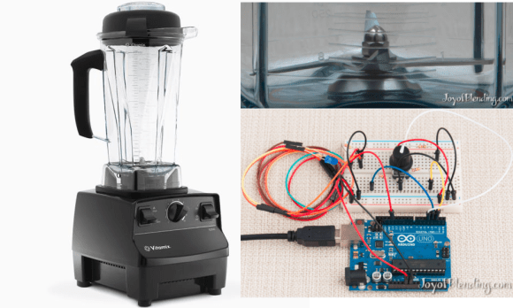
Some people really love their smoothies. We mean really, really, love smoothies and everything about making them, especially the blenders. [Adam] is a big fan of blenders, and wanted to verify that his Vitamix blenders ran as fast as the manufacturer claimed. So he built not one, but two speed measuring setups. Scientific blender measurement method requires one to cross check their results to be sure, right?

Measuring the speed of a blender is all about the RPM. Appropriately, [Adam’s] first measurement tool was an LED based stroboscope. Stroboscopes have been around for hundreds of years, and are a great way to measure how fast an object is rotating. Just adjust the speed of a flashing light until the rotating object appears frozen. The number of blinks per second is then equal to the Rotations Per Second (RPS) of the object being measured.Multiply by 60 seconds, and you’ve got RPM. [Adam] used an Arduino as the brains behind his stroboscope. He wired a dial up on his breadboard, and used it to adjust the flash rate of an LED. Since this was a quick hack, [Adam] skipped the display and just used the Arduino’s USB output to display speed measurements on his laptop.

There are possibilities for error with stroboscopes. [Adam] discovered that if the stroboscope was flashing at a multiple of the blade’s rotation speed, the blades would appear frozen, and he’d get an erroneous RPM value. Thankfully, [Adam’s] Vitamix had asymmetric blades, which made the test a bit easier. He calculated his blades to be spinning at 380 RPS, or 23,000 RPM. Not satisfied with his results, [Adam] brought out Audacity, and ran a spectral analysis of the blender in operation. He found a peak at 378Hz, which was pretty darn close to his previous measurement. Since the blender has a 4 inch blade this all works out to a blade tip speed right around the claimed value of 270 MPH. We’re glad [Adam] found an answer to his blender questions, but our personal favorite blender hack still has to be the V8 blender created by the Top Gear crew.   [via HackerNews]

Gif Player Does It Using Paper Medium

Ditch that fancy wide-format LCD monitor and go back to the days when animation was made up of moving frames played back by a specialized device. [Pieterjan Grandry] built this gif player which does just that. The frames of the animation are printed on a paper disk. When spun and viewed through a looking hole the same size as one frame an animated image is formed.

If you know a thing or two about how movie projectors work you might have a raised eyebrow right now. To make the animation smooth you need a way to hide the changing of the frames. With a projector there’s usually a spinning shutter (like a fan) that covers the transition between frames. In this case, [Pieterjan] has mounted the case of the gif player far enough in front of the paper disk that the image is in shadow, making it hard to see. A microcontroller responsible for the speed of the spinning disk flashes some white LEDs with precise timing which gives light to each frame at just the right time.

This is really a 2D equivalent to the 3D stroboscope we saw a few days ago.

[Thanks Agtrier]

Stroboscope Project Uses Optical Drive Motor And Arduino

In the quest for a diy laser cutter made from DVD burner parts (that hack’s still in the works) this guy ended up with a junk box full of optical-drive leftovers. He put some of that surplus to good use by building this stroboscope. As the media spins, the white LED just out of focus in the foreground strobes to freeze the little black figure in the same place. The effect, as seen in the video after the break, is a dancing figure created by the optical illusion.

This is the same concept as that amazing 3D rowing skeleton build, but scaled down greatly. Each of the silhouettes seen above are slightly different, showing one pose that makes up a frame of the overall animation. They’re laser cut, but some careful paper-craft could probably accomplish the same thing. Assuming you could keep them from warping when spinning at high speeds.

Continue reading “Stroboscope Project Uses Optical Drive Motor And Arduino”

Easy DIY Stroboscope

stroboscope_output

Looking for something to do in his downtime, [Mista Sparkle] decided that building a simple stroboscope was in order. He already had a set of six LEDs connected to his Arduino from a previous project, so he added a potentiometer to control the rate at which the LEDs flashed, and dug into the IDE.

During his build he discovered that using the Arduino millis() function at high speeds provides terrible resolution, while using the micros() function exclusively limits his low end measuring capabilities. He desired a better range of measurement, so his program was broken into main functions: One which measures the LED flashing frequency in milliseconds and another that measures the LED flashing frequency in microseconds. This allowed him to gauge rotational frequencies from 577 to 30,000 RPM.

[Mista Sparkle] admits that he is not yet well-versed in driving displays with the Arduino, so he views his readings over a serial connection on his PC. Hopefully we’ll see an updated version with those features in the near future.

Stroboscope LED Fan Clock


[sprite_tm] sent in one of his latest little adventures – and I love it. To create his stroboscope fan clock, he put a couple of red and green clock hands onto a standard PC fan(I love Panaflo fans), then he built a circuit to strobe a RGB LED to create a set of virtual clock hands on the spinning fan. An ATTiny2313 does all the work, with the help of some transistors to drive the LEDs.