RFID Jukebox For The Kids

[Dominik] built a fun musical toy for his daughter [Anna]. It’s a jukebox that lets her play her favorite tunes using RFID tags to select between them.

The project is simple, yet robust. The enclosure is a wooden craft box that you can pick up for a couple of bucks. Inside there’s an Arduino with a Wave Shield which handles the audio playback. An RFID reader takes input from the set of card-tags he procured. An internal Lithium battery powers the device, with a USB port for charging.

Sure, those guts have some cost involved in them. But there’s no LCD which can be broken, and we thing the boards will hold up well to abuse if mounted correctly. Plus there’s a lot of future potential here. When we saw the cards we thought of those toys which make the animal sounds (“what does the cow say… mooo”). This could be used for that with really young children. Then repurposed into this jukebox as they get a bit older. If you put the guts in a new enclosure it will appear to be a brand-new toy, right?

See a demo of the project in the clip after the break.

Continue reading “RFID Jukebox For The Kids”

Increasing A Digital Servo Motor’s Range Of Motion

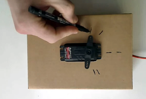
Unhappy with the 120 degree range of movement for this digital servo motor [Malte] set out to expand its flexibility. He settled upon a hack that alters the feedback potentiometer in order to give the motor a wider range (translated).

The test video (embedded after the break) shows tick marks for before and after his alterations. You can see that the wider tick marks get much closer to the 180 degree range he’s interested in. The control method is no different than it was before, the internal circuitry is still listening for a control signal with pulses between 1 and 2ms to establish the position of the servo horn. [Malte] added resistors on the two outside legs of the feedback potentiometer. This is what that control circuit measures in order to judge the position of the servo horn. He’s using 1.6k Ohm resistors in this demonstration. But he didn’t just drop them in willy-nilly. His writeup discusses the calculations he used to determine the target voltage for the motor position he wants.

Continue reading “Increasing A Digital Servo Motor’s Range Of Motion”

From Reference Design To USB Sound Card

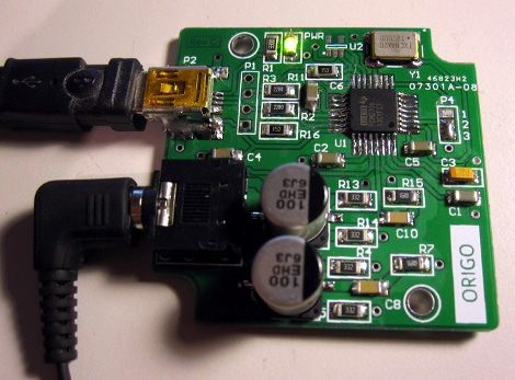
[Entropia] decided to try his hand at rolling is own sound card. He picked out a DAC chip, started his prototyping by studying the reference design from the datasheet, then went through several iterations to arrive at this working model.

He chose to base the board around the PCM2706. It’s a digital to analog converter that has built-in USB support; perfect for his needs. It’s got a headphone amplifier, but is also capable of putting out S/PDIF signals for a digital amplifier to pick up and use. Not bad for a part that can be had for right around eight bucks.

The first PCB he designed had a few electrical and footprint errors. But he was able to get it to run by adding some point-to-point jumpers, and bending the legs of his capacitors to fit the board area. With those issued accounted for he ordered a second batch of boards. These went together nicely, but the headphone output was incredibly loud. Turns out the filtering circuit had the wrong resistor and capacitor values. Changing them around, and swapping the audio output so that the correct channels were patched to the audio jack brings it to the first release version seen above.

A Better Dust Skirt For Your CNC Mill

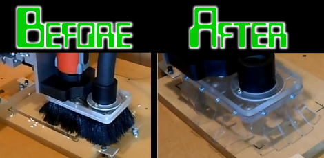
[Joshendy] wanted to get a better look at the cutting head on his CNC mill when it was running. The problem is that the rotating blades throw up a lot of junk which you don’t want flying around the shop so they’re usually surrounded with a shroud connected to a shopvac. He just milled is own transparent dust skirt to solve the problem.

The original dust skirt uses black bristle brushes to contain the waste from the cut. In addition to obscuring your view of the cutter this didn’t do a very good job of containing bits and pieces. The solution seen on the right uses clear, flexible PVC as the skirt. The video after the break details the build process. [Joshendy] cut out a replacement plate which is then fitted with magnets to connect to the cutter. The skirt is affixed to that plate with a series of screws, making it easy to replace if it ever wears out.

Continue reading “A Better Dust Skirt For Your CNC Mill”

An Inside Look On How Reed Switches Are Manufactured

reed-switch

[York] wrote in to share a video he stumbled across while researching reed switches and relays, which documents the tightly controlled process through which they are produced. Like many other electronic components out there, we usually don’t give a lot of thought to how they are made, especially when the final cost is relatively small.

For something often taken for granted, the process is an incredibly precise one, requiring a clean room environment the entire way through. The video follows the production line from beginning to end, including the soft annealing of the contacts to remove magnetic remanence, the sputtering process that applies sub-micron thick conductive coatings to the contacts, through the laser cutting and sealing of the glass tubes that make up the body of the switch.

At the end of the day, the video is little more than a manufacturer’s promotional video, but it’s worth the 8 minutes it takes to watch it, if only to satisfy your curiosity as to how they are made.

Continue reading “An Inside Look On How Reed Switches Are Manufactured”

“Machining” Copper Parts Using Cupric Chloride

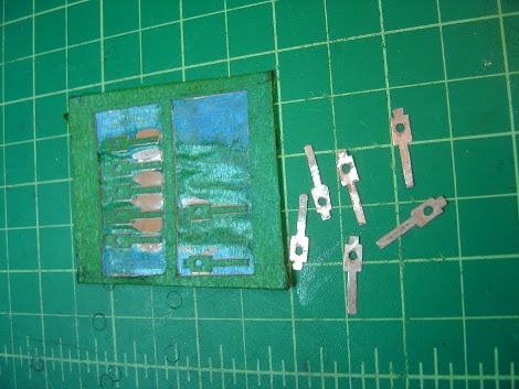
[Ben Ardwin] was asked by a friend to help fix an old motor. It needed a new set of brushes. They’re just thin pieces of copper that mount on the motor housing and contact the commutator. The metal is so thin he thought he’d try fabricating replacements by dissolving copper stock.

This is not copper clad board; the raw material used in PCBs that has a copper-covered fiberglass substrate. It’s just thin sheets of copper stock. [Ben] started by covering top and bottom with painter’s tape. This will act as a resist for the chemical etchant. He headed over to the laser cutter to remove the tape mask around the outline of the parts. From there it’s into the Cupric Chloride for about two hours.

The etched parts are a bit rough around the edges so he cleaned them up by hand using a file. When writing to us about the process he suggests a few improvements. The tape used for masking wasn’t ideal and he would try a different method. He would also remove less area around the parts to help speed up the process.

This technique is a really becoming popular as a home-fabrication tool. Recently we’ve seen etched copper used to make a faceplate for an enclosure, and a translucent template for a clock.

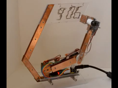
Robotic Doodle Clock

This clock has a robotic twist to it. It will show you the time by drawing it in dry-erase marker. There’s a bit of play in the arm joints and some loose motor precision which results in a wavy font that prompted [Ekaggrat] to name his project the Doodle Clock.

The shape and building material used here really make the timepiece look great. We think if the arm holding the acrylic writing surface had been at right angles this would not look nearly as pleasing. The video after the break shows the bot in action, at first flexing its wrist to switch back and forth between marker and eraser. From there it starts to draw the time, tracing the segments of each digit multiple times to achieve a readable number. The entire thing is driven by an Arduino compatible board mounted on the base of the clock.

This reminds us of that felt-tipped Turing Machine. A variation on that would also make a really nice clock display.

Continue reading “Robotic Doodle Clock”