A One-bit Processor

Put on that abstract thinking cap, get out the pen and paper, and spend some time figuring out how this one-bit processor works. [Strawdog] came up with the concept one day during his commute to work (don’t worry, he takes the train… much safer than [Dave Jones’] frightening drive-time podcasts). He sketched it out on paper to make sure he knew where he was going with the project, then collaborated with Legion Labs to implement it in processing as an easier way to visualize its functionality. Since it’s one-bit there’s only room for one instruction. That instruction is a copy, then branch-if instruction. It copies the current bit to one address, and if that bit was one, it branches to a second address.

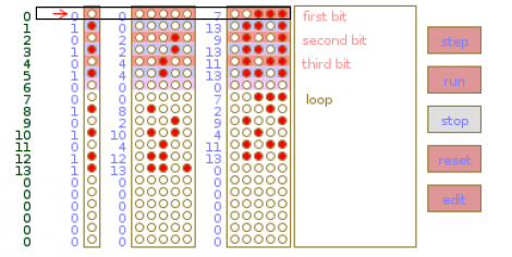
Going a bit fast for you? We think the description is fairly good, but if you can’t quite put it together from the article’s description, you may want to build this 2-bit paper processor and learn how it works first. It should teach you the basic concepts you need to understand the 1-bit version. As you can see in the image above, there’s also a single-step feature in the processing example that lets you analyze the effects of each instruction during program execution.

Rolling Digit Clock Is A Wonderful Piece Of Engineering

A long time ago and on a scrounging trip he barely remembers, [Victor] bought a quartet of digits from an old Dutch Railways clock. These antique displays used a strip of plastic coated cloth that rolls around itself with the help of a motor to display the digits 0 through 9. It’s been many years, but [Victor] finally got around to building a clock out of these single digit displays and we’re loving the results.

Because these displays were manufactured in a time when mechanical devices were king, [Victor] had to slightly modify each digit so they could display numbers with the help of a continuous rotation servo. The four servos are controlled by an Arduino – each digit changing one at a time to reduce current consumption – and a magnet and reed switch was added to each digit so the numbers could be repeatedly displayed.

Before [Victor] replaced the plastic servo gears with metal cogs, the clock was quite noisy. He’s since put each digit underneath a bell jar (actually a vase turned upside down), and we’ve got to say that [Victor] has a nice clock on his hands. Check out the videos of the clock changing digits to display the time after the break.

Continue reading “Rolling Digit Clock Is A Wonderful Piece Of Engineering”

Microsoft Shows Off Their Transparent 3D Desktop Prototype

We think most would agree that the Microsoft Kinect is a miraculous piece of hardware. The affordable availability of a high-quality depth camera was the genesis of a myriad of hacks. And now it seems that type of data is making an intriguing 3D display possible.

What you see above is a 3D monitor concept that Microsoft developed. It starts off looking much like a tablet PC, but the screen can be lifted up toward the user whose arms reach around it to get at the keyboard underneath. There is as depth camera that can see the hands and fingers of the user to allow manipulation of the virtual environment. But that’s only part of the problem. You need some way to align the user’s eyes with what’s on the screen. They seem to have solved that problem too, using another depth camera to track the location of the user’s head. This means that you can lean from one side to the other and the perspective of the virtual 3D desktop will change to preserve the apparent distance of each object.

Don’t miss the show-and-tell video after the break. As long as there’s only one viewer this looks like a perfect non-glasses alternative to current 3D hardware offerings. Continue reading “Microsoft Shows Off Their Transparent 3D Desktop Prototype”

Billiards Concepts Plied To Position Acoustic Panels

If you know your way around a pool table you should be able to apply those skills to improving the sound of your home theater. [Eric Wolfram] put together a post that discusses the issues caused by unwanted sound reflections and shows how to position acoustic tiles to solve the problem.

This is a companion post to his guide on building your own acoustic tiles. Don’t worry if you haven’t gotten around to doing that yet. With just a wood frame, dense fiberglass, and some fabric they’re simple to build. They’re also easy to hang but until now you might have just guessed on where they should go.

Once you have all of your speakers and seats in position grab a mirror and some post-it notes. Take a seat as the viewer and have a friend operate the mirror as seen above. With it flat against the wall, mark each spot with a sticky-note where you can see a reflection of one of the speakers. Finding the reflection points is just like lining up a bank shot in Billiards. With five speakers (5.1 Surround Sound) and six surfaces (walls, ceiling, and floor) you should be able to mark 30 reflections points. Now decide how wild you plan to go with the project. The best result will address all 30 reflection points, but you can get by with just the front marks if you’re a bit more conservative.

WAV Playback With An ATmega32

[Vinod Stanur] just finished another hobby project by building a WAV audio player using a microcontroller. He had started development a while back using a PIC microcontroller. But the chip he was using didn’t have enough SRAM to allocate as a playback buffer. When he got his hands on an ATmega32 his mind turned back to the project and he saw it through to the end.

He takes advantage of what he learned on several earlier builds. He’s using a TV remote as input, just like his Snake game did. Storage is provided by an MMC card, a trick he perfected with this voice recorder project. Instead of using a FAT library, he uses his own code to read the linked-list (File Allocation Table) for sector addresses, then he parses the WAV header and processes the file accordingly.

Playback uses two 512 byte buffers. One is feeding the output while the other is being populated from the memory card. When the output buffer is exhausted the two are swapped and the process continues. You’ll find [Vinod’s] demo of the project after the break.

Continue reading “WAV Playback With An ATmega32”

Wardriving For Zigbee

Wardriving started out as a search for unprotected WiFi access points before hot spots were prevalent. And so this ZigBee protocol wardriving hardware which [Travis Goodspeed] put together really gives us a sense of nostalgia for that time. Don’t get us wrong, we love our pervasive WiFi access and don’t wish to go back to simpler times. But if the radio signals your looking for are scarce, locating them provides a challenge.

Regular readers will recognize that [Travis] is interested in all things RF. One of his projects included sniffing wireless keyboard packets out of thin air and displaying them on the screen of his Nokia N900. This is right along those lines but he’s upgraded to an N9 phone for the display hardware. He switched up the RF hardware, using a TelosB (a board he’s already familiar with) to get on the 802.15.4 ZigBee spectrum. This dev board has an expansion port which let him use an RN42 module for wireless communications with the phone. This means the sniffing hardware can be hidden away in a backpack or jacket. After all, nobody will question someone walking around staring at a smart phone.

Semaphore Signal Replica Perfect For The Train Buff In Your Life

semaphore-signal

[John Philip’s] brother has a sizable room set aside for his model railroad setup, and he was looking for something interesting to add to his brother’s collection. Rather than construct something for the railroad itself, he decided that an early 1900’s-style semaphore railroad signal would make a great novelty item for the room.

The project started with [John] scouring the Internet for colored signal lenses. Once he found a set that worked for him, he crunched some numbers to ensure that the rest of the semaphore box stayed true to original scale. Inside the signal’s case you will find a small regulator board for his light source, an Arduino, and a motor controller board to actuate the arm.

To ensure that the signal arm is always perfectly positioned, he installed a pair of reed switches on either side of the case, enabling the Arduino to auto-calibrate the signal’s position each time it is powered on. At first, this control scheme might strike you as a bit over the top, but we really like the fact that the signal can always configure itself to function perfectly, even if someone tinkers with/bumps into/moves the arm at any point.

Be sure to stick around to see a short video of the semaphore signal in action.

Continue reading “Semaphore Signal Replica Perfect For The Train Buff In Your Life”