THP Entry: OpenMV

OpenMV

The future is a scary place, full of robots, drones, and smart appliances with cameras and vision systems that will follow your dog, your child, or your face around, dutifully logging everything they see, reporting back to servers, and compiling huge datasets that can be sold to marketing companies. We’re not too keen on this view of the future, but the tech behind it – cheap cameras in everything – is very cool. [Ibrahim] is doing his part to bring about the age of cheap cameras that are easy to interface with his entry to The Hackaday Prize, the OpenMV.

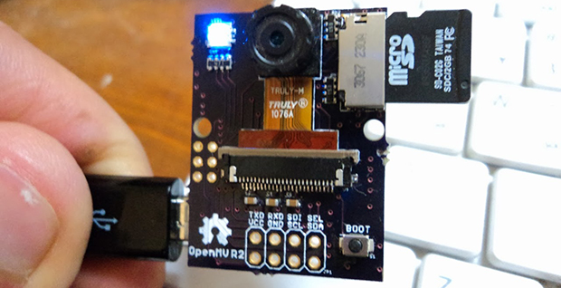
The idea of a digital camera that is easy to interface with microcontrollers and single board computers isn’t new. There are serial JPEG cameras and the CMUcam5 Pixy, but they cost somewhere around $70. It’s not something you would design a product around. [Ibrahim]’s OpenMV costs about $15, and offers some interesting features like on-board image processing, a huge amount of RAM, and even a wireless expansion thanks to TI’s CC3000 WiFi module.

Currently, the OpenMV is capable of doing face detection at 25fps, color detection at better than 30fps, all thanks to the STM32F4 ARM micro running at 180MHz. There’s support for up to 64MB of RAM on board, with IO available through serial, SPI, I2C, USB 2.0, and WiFi.

It’s an interesting project on its own, but the really cool thing about this build is the price: if [Ibrahim] can actually produce these things for $15 a pop, he has an actual product on his hands, one that could easily be stuffed inside a drone or refrigerator for whatever cool – or nefarious – purposes you can imagine.


SpaceWrencherThe project featured in this post is an entry in The Hackaday Prize. Build something awesome and win a trip to space or hundreds of other prizes.

Droning On: Choosing A Flight Controller

do4 The flight controller is the nerve center of a drone. Drone flight control systems are many and varied. From GPS enabled autopilot systems flown via two way telemetry links to basic stabilization systems using hobby grade radio control hardware, there is an open source project for you.

Modern drone flight controllers can trace their roots back to R/C helicopters. Historically, R/C planes were controlled directly by the pilot’s radio. Helicopters added a new wrinkle to the mix: tail rotors. Helicopters use their tail (or anti-torque) rotor to counteract the torque of the main rotor attempting to spin the entire helicopter’s body. It all works great when the helicopter is hovering, but what about when the pilot throttles up to fly out? As the pilot throttles up, the torque increases, which causes the entire helicopter to do a pirouette or two, until the torque levels out again. The effect has caused more than one beginner pilot to come nose to nose with their R/C heli.

The solution to this problem was gyroscopes, heavy brass spinning weights that tilted in response to the helicopter’s motion. A hall effect sensor would detect that tilt and command the tail rotor to counteract the helicopter’s rotation. As the years wore on, mechanical gyros were replaced by solid state MEMS gyros. Microcontrollers entered the picture and brought with them advanced processing techniques. Heading hold gyros were then introduced. Whereas older “rate only” gyros would drift, weathervane, and wiggle, heading hold gyros would lock down the helicopter’s nose until the pilot commanded a turn. These single axis flight controllers were quickly adopted by the R/C helicopter community.

Today’s flight control systems have many sensors available to them – GPS, barometric pressure sensors, airspeed sensors, the list goes on. The major contributors to the flight calculations are still the gyros, coupled with accelerometers. As the name implies, accelerometers measure acceleration – be it due to gravity, a high G turn, or stopping force. Accelerometers aren’t enough though – An accelerometer in free fall will measure 0 G’s. Turning forces will confuse a system trying to operate solely on accelerometer data. That’s where gyros come in. Gyros measure rate of rotation about an axis. Just as our helicopter example above covered yaw, gyros can be used to measure pitch and roll of an aircraft. A great comparison of gyros and accelerometers is presented in this video from InvenSense.

Stay with us after the break for a tour of available flight controllers and what each adds to the mix. Continue reading “Droning On: Choosing A Flight Controller”

The Hovering, Holographic, Star Wars Display

Tweetergif

While we’re still a long way off from the Star Wars telepresence holographic displays, this build over on the Projects site is the closest we’ve seen yet. Even better, it can be built in a garage for not much money.

Inside the Hoverlay are a few fans and a pair of ultrasonic atomizers that turn water into an extremely fine mist. The fans pull this vapor up through the base of the display and through simple drinking straws to create a laminar sheet of water vapor. Put a projector behind this thin sheet of vapor, and you have a display, seemingly floating in mid-air.

The base of the display can be scaled up, simply by putting several units together in a line. It’s still just a prototype – future versions will improve the stability and reduce the thickness of the fog layer – but it’s still a very cool build for a custom holographic display.

Continue reading “The Hovering, Holographic, Star Wars Display”

DIY Newton’s Cradle Uses Parts Designed On A Smart Phone

Injection Molded Parts

As far as physics demonstrations go, the Newton’s Cradle is probably one of the most recognizable. Named after Sir Isaac Newton, the Newton’s Cradle demonstrates the law of conservation of momentum using swinging ball bearings.

[Scorchworks] decided he wanted to build his own Newton’s Cradle. The frame appears to be cut from MDF or particle board and then screwed together. That material is really easy to obtain and also to work with using inexpensive tools. The tricky part was the ball bearings. Most of the time when you see a Newton’s Cradle, the ball bearings have a small hole drilled in the top with an eye hook attached. The string is then attached to the eye hook.

[Scorchworks] decided to do something different. His plan was to make custom injection molded plastic rings that would fit perfectly around the ball bearings. The most interesting thing is that he designed the injection molding plates entirely on his smart phone while at his child’s baseball practice. To do this, [Scorchworks] used his own Android app, ScorchCAD. ScorchCAD is a free clone of OpenSCAD that is designed to run on Android devices. Most of the functionality of OpenSCAD has been implemented in ScorchCAD, though not all functions work yet. You can find a list of all the supported functions on the project’s website or in the Google Play store.

Once the plates were designed within ScorchCAD, [Scorchworks] exported the STL file and then used Meshcam to generate the gcode for his CNC milling machine. Once he had the plates machined, he just placed the ball bearing into the mold and injected the molten plastic around it. The plastic formed a perfectly shaped ring around the bearing with small loops for the string. [Scorchworks] repeated the process several times to get all of the ball bearings finished.

Finally, the bearings were strung up using some fishing line. A Newton’s Cradle is very sensitive to the positioning of the ball bearings. To account for this, [Scorchworks] tied each end of the fishing line to two different screws on top of the cradle. This way, each screw can be tightened or loosened to adjust the position of each ball bearing.

How A Maker Proposes

proposal

[Sefi Attias] just sent us a heartwarming little video of how he proposed to his girlfriend [Tania] — using a little help from technology and other makers.

As a maker, [Sefi] was always building things which impressed [Tania], so he thought it was only fitting to make the proposal a one-of-a-kind maker experience.

He started by designing the engagement ring himself, to be 3D printed. It’s an amazingly complex little thing made up of the repeating words of the quote “I will betroth you to me forever”. It was almost too complex in order to print — but they managed to do it in wax, which allowed them to create a mold and then cast the final part in white gold. Once complete, they set a diamond in place to cap it all off.

The second step was the proposal, which was made possible using a quadrotor, a strip of RGB LEDs, and a long camera exposure. To show it off in real-time to [Tania] they setup a projector and screen on the side of the street, providing a surreal window into the park behind them. It was all made possible with the help from over 20 people from the XLN Makerspace and SkyLens (the quadrotor people).

Oh yeah, and she said yes.

Continue reading “How A Maker Proposes”

Designing And Printing A Custom Enclosure

enclosure

So you know how to design a circuit board, assemble the parts, and have a functional device at the end of a soldering session. Great, but if you want to use that device in the real world, you’re probably going to want an enclosure, and Tupperware hacked with an Exacto knife just won’t cut it. It’s actually not that hard to design a custom enclosure for you board, as [Glen] demonstrates with a custom 3D printed project box.

[Glen]’s board, a quad RS-422 transmitter with a PMOD connector, was designed in Eagle. There are a vast array of scripts and plugins for this kind of mechanical design work, including the EagleUP plugins that turn an Eagle PCB into a 3D object that can be imported into SketchUp.

Taking measurements from Eagle, [Glen] designed a small project box that fits the PCB. A few standoffs were added, and the board itself was imported into SketchUp. From there, all he needed to do was to subtract the outline of the connectors from the walls of then enclosure for a custom-fit case. Much better than Tupperware, and much easier than designing a laser cut enclosure.

Once the enclosure was complete, [Glen] exported the design as an STL, ready for 3D printing or in his case, sending off to Shapeways. Either way, the result is a custom enclosure with a perfect fit.


Industrial Light Painting Steps It Up A Few

industrial light painting

What would you do if you had access to an industrial ABB IRB 6640 robot? We’d probably make a giant 3D printer, but if you’re [Jeff Crossman] and [Kevyn McPhail], you’d make one of the most advanced light painting setups we’ve ever seen.

The setup itself is really quite simple — a single RGB LED is connected to a Teensy microcontroller on a tool-head for the robot — controlling the robot is the hard (fun?) part. To create the images, [Jeff] had several students come in to have their photographs taken using a Microsoft Kinect. This allowed him to create an RGB point cloud for the robot to recreate.

Using Rhino he created the tool paths required for the robot to build up a floating 3D image of the students for the camera taking the long exposure. Each demonstration made use of ~5000 points, which takes the robot arm about 25 minutes to place.

It’s a fascinating video, and yes it does seem like a bit of overkill, but hey — why not?

Continue reading “Industrial Light Painting Steps It Up A Few”