Arduino IDE Forked

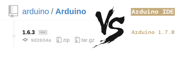
As if it weren’t confusing enough in the Arduino world these days, now we’re going to have to deal with conflicting version numbers for the IDE. Yup, it’s been forked. Arduino LLC is offering a recently-updated version 1.6.3 at arduino.cc, but Arduino SRL has bumped up the version number to 1.7.0 at arduino.org. The conflict in naming and versioning has not gone unnoticed.

For those of you who’ve been living under a rock lately, the company that developed the Arduino (Arduino LLC) and the company that’s been manufacturing most of the hardware (Smart Projects SRL, now Arduino SRL) have stopped cooperating, filed a bunch of lawsuits, and now maintain separate websites.

According to this article (Google translate here) the versions don’t differ by much, and the 1.7.0 IDE may even be a step backwards versus 1.6.3. It certainly seems to us that the majority of the active developers in the Arduino project have been sticking with [Massimo Banzi] and the Arduino LLC camp. Of course, everything’s open source and there’s nothing stopping Arduino SRL from porting worthwhile IDE changes across to their version of the codebase.

It doesn’t take a clairvoyant to sense that this may be in response to the warning about non-licensed boards that was included in the “official” 1.6.1 release. Nor does it take a psychic to foresee confusing times ahead.

If you’re interested in doing some code-sleuthing, have a look at the two versions and leave a comment below letting us know of any substantive differences you unearth.

Thanks [Kai], and via [Golem.de].

3D Printed Space Invader

3D Printing Different Colors With A Single Extruder

Let’s be honest, multi-extruder 3D printers don’t work the greatest — even MakerBot decided to get rid of the feature in their latest line of printers. So what are you going to do when you want to print a multi-colored object with your trusty single extruder? Pause the print like a savage and exchange the filament? No, no, it’s much easier than that — well, you’re still going to have to switch the filament.

[Jana Marie] has put together a simple script in OpenScad to split up 3D files into layers in order to facilitate printing in multiple colors (or even materials). You load in the file, tell it the print height you want to do, export, convert to G-Code, print, rinse, repeat. In between the layers you have time to purge the extruder, remove any excess skirt or support material, and then hit print again. Quite a bit easier than hitting pause and jogging the extruder out of the way (while avoiding plastic dribble coming out of your extruder!).

Meanwhile if your prints get interrupted — or fail a lot — you might be interested in this project by a group of MIT researchers. It’s an add-on for 3D printers that uses a laser scanner to evaluate how much of the part was printed, allowing you to restart a print that failed!

3D Printed Pogo Pin Programmer

The new hotness for Internet of Things hardware is the ESP8266. Alone it can connect to a WiFi network, but it doesn’t really have a lot of output options. Paired with an ATMega, and you really have something. That’s the philosophy behind the WIOT board, and when [Chris] was assembling these boards, he needed a way to flash firmware. The board has an unpopulated ISP header from the assembler, so pogo pins are the answer. How do you make a pogo pin jig? With a 3D printer, of course.

The ISP header wasn’t populated to give the board a slim profile, but this means a jig of sorts would be needed to program the WIOT. The first attempt was buying a few pogo pin adapters from Tindie, but this was terribly uncomfortable to hold while the board was being programmed.

To fix this problem, a small clip device was rigged up, printed out, and used for programming. Interestingly, this clip has a very deep throat, and a few holes used for bolting on a separate programmer. This shows a lot of forward thinking: the programmer can be reused for different boards with completely different layouts and programmers. If the next revision of the WIOT needs a JTAG header to program the micro, the problem of programming it is already covered.

How To Build A Thermocouple Amplifier

A Thermocouple is a terrific way to measure temperature. The effects of temperature change on dissimilar metals produces a measurable voltage. But to make that measurement you need an amplifier circuit designed for the thermocouple being used.

Linear Technology LTC 1049 Low Power Zero-Drift Operational Amplifier with Internal Capacitors
Linear Technology LTC 1049 Low Power Zero-Drift Operational Amplifier
with Internal Capacitors

While researching “Zero Drift Amplifiers” as a follow-up to my video on Instrumentation Amplifiers I noticed the little schematic the front page of the LTC1049 datasheet which is shown here. I thought it was an ideal example of an analog application where some gain and some “gain helper” were needed to accomplish our useful little application of amplifying a thermocouple probe.

In the video I don’t really talk much about the thermocouples themselves other than the type I see most of the time which is type K. If you’re not already familiar with the construction of these probes you can find an informative write-up on thermocouples and the different types on the Wikipedia page and you might also want to check out the Analog Devices app note if you would like to know more. What I will cover is a reliable and precise way to read from these probes, seen in the video below and the remainder of the post after the break.

Continue reading “How To Build A Thermocouple Amplifier”

Automated Die Testing

Are the contents of a Crown Royal bag fair? No, they never are. What about dice? In a quest for good randomness, [Apo] designed and built an automated die tester. Not only does it shake the die up, it captures images so real, actual statistics can be done on each individual die.

The setup is a n acrylic box made with BoxMaker attached to a 3D printed adapter for a stepper motor shaft. Randomizing the die happens exactly like you think it would: a stepper shakes the box, and a camera underneath takes a picture. With a bit of computer vision, this image can be translated into a number, ready for the statistics package of your choice.

There were only 559 rolls before the 3D printed mess of duck tape fell apart, but a test of the distribution revealed this die to have a 92% probability that it is fair. That’s not good.

Creating a cheating die is much more interesting, and to find out if he could do it, [Apo] stuck a die in an oven at 100° C for a few minutes. Surprisingly, the fairness of the die got better, suggesting it’s possible to correct an un-fair die. Putting it back in the oven after that threw the fairness out of the window but there was still no visual difference between this modified die and the original stock die.

More Power For Raspberry Pi USB Ports

Since the Raspberry Pi 2 was released, everyone building RetroPi emulators has been graced with four USB ports. For those of us doing useful stuff with the Pi, those ports are a little anemic: you can’t plug in a webcam and a WiFi module at the same time without suffering CPU brownouts. The maximum current all USB peripherals can draw from the USB port is 600mA. By changing a value in the /boot/config.txt file, this current limit can be increased to 1.2A for all four ports.

Pisquare
The yellow line traces the signal from the GPIO to the USB power switch.

Because the USB current limit is set in software, there must be a few bits of hardware that do the actual work. Tucked away below the right hand of the GPIO header is the hardware that does exactly that. It’s an AP2253 current-limited power switch (PDF), and the current is adjustable by tying a resistor to pin 5 on the chip.

Pin 5 on the AP2253 is connected to two resistors. One resistor goes directly to a ground plane, while the other is switched through a FET. The gate of this FET goes to another resistor, and when a GPIO pin is high, these resistors are wired in parallel. This means the resistance is halved when the GPIO pin is high, doubling the current limiting circuit in the AP2253.

This setup provides a relatively easy mod to increase the current limiting of the USB ports so they can provide 4x500mA, meeting the USB spec. The AP2253 power switch’s current limiting can be set by a single resistor, anywhere from 10kΩ to 232kΩ. By removing R50 and R4, and replacing R50 with a 10kΩ resistor, the current limiting of the AP2253 switch will be set to its maximum, 2.1A. Divide that by four, and you have 500mA per port, just like every other computer on the planet.

There is a reason the Raspberry Pi foundation set the current limiting of the USB ports so low. The Pi was originally intended to run off of a micro USB phone charger. There aren’t many phone chargers out there that will supply more than 1A, and the CPU and related peripherals will take half of that. If you’re going to change the /boot/config.txt file, you’re going to need a beefy power supply. Increasing the current limiting of the USB ports to 2A will require an even bigger, beefier supply.

Internet Of Cowbell

If this is a sign of the times, the Internet of Things promises a lot of entertainment for hackers who can come up with wacky ideas and interactive projects. [Brandon] built a cowbell that rings when you tweet #morecowbell. Why? Because!

On the hardware side it is quite simple, and can be built in a number of different ways depending on the parts you have lying around. [Brandon] used an Electric Imp and its corresponding breakout board. A Sparkfun mini FET shield helps drive the solenoid that hits the cowbell. And because he had one lying around, he added a counter across the solenoid to count the number of times the Twitterati have rung the Cowbell.

The code for the Electric Imp consists of two parts – the “agent code” that runs on a server in the Electric Imp Cloud and the “device code” that runs on the imp itself – and is available at this Git link. Once you tweet with the hashtag, the Cowbell replies back, randomly selecting one from a list of stored responses. Would be nice to see a video of the Cowbell in action. And if it can be made to play the Salsa beat.