Let’s say you’ve recently bought a lathe and set it up in your shop. Maybe you’ve even gone and leveled it like a boss. You’re ready to make chips, right? Well, not so fast. As real machinists will tell you, you can use all the levels and lasers and whatever that you want, but the proof is in the cut. Precision leveling gets your machine in the ballpark (machinists have very small ballparks) but the final step to getting a machine to truly perform well is to cut a test bar. This is a surefire way to eliminate any last traces of twist in the bed.
There are two types of test bars. One is for checking headstock-to-ways alignment, which is what we’re doing here. There’s another type used for checking tailstock alignment, but that’s a subject for another day.
We start by chucking some stock. You want something of a substantial diameter, because we’re going to have a lot of unsupported stick-out, something you would normally never do. The stock needs to be as rigid as possible on its own. The more stick-out you have, the more precise your measurement of bed twist will be, but the test becomes impossible if stick-out is too much for the stock to remain rigid while cutting. It’s a tricky balance. For this demo on my small bench-top machine, I’m using 1-¼” diameter stock, 5″ long. For a large floor-standing machine, 2″ diameter stock around 10″ long is a good place to start.
Dial it in as close as you can in the four-jaw chuck. The more run-out we eliminate now, the quicker and easier this test will be. If you have stock with a machined surface, that’s ideal, but cold-rolled stock from the factory is generally fine. I’m using mild steel here, but something like 12L14 free-machining steel would make it easier to get a good finish (which helps with the measurements).
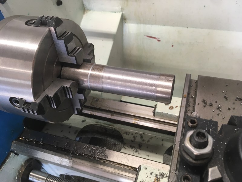
The general idea is that we’re making a barbell shape. We’ll make high-precision cuts on the ends, while leaving a narrower area in the middle that we can easily skip over.
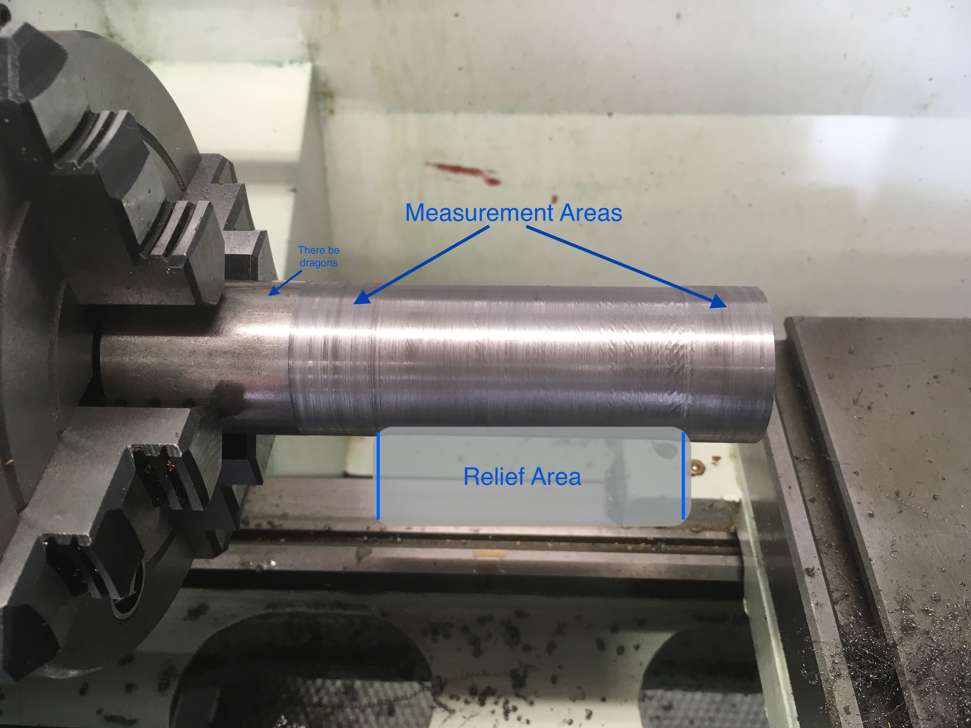
With the stock dialed in, turn down a relief area in the center of the bar, leaving about an inch on each end untouched. We’ll only be measuring the ends, so the middle section will just be in the way. Making a relief also minimizes tool wear between cuts (which would affect our test results). A relief of 30-50 thou is sufficient. We want just enough room to clear a few test cuts on each end. Don’t relieve too much, because we need that rigidity in the stock.
Note that we’re not using the tail stock for support here. This is important because the tail stock introduces its own set of variables that affect alignment. We’re only testing headstock-to-ways alignment, so we can’t use the tailstock. This means we have to make very light cuts because our rigidity is very low.
With the relief made, we can now take very light cuts in the two measurement areas. We want just enough to clean up the surface all the way around (so we know we’re inside any runout in the chuck). I’m making two-thousandth cuts on each pass here. Make your pass on both measurement areas, without touching the cross-slide in between. Stop the machine at the end and measure, then wind the carriage back and do another cut as needed.
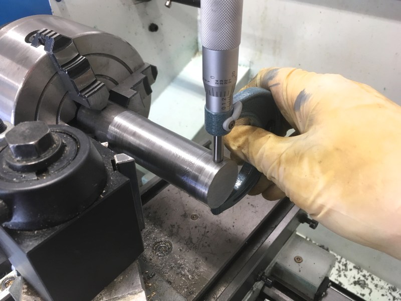
Once you have a clean cut on both measurement areas, compare the diameters with a high quality micrometer. If they are different, the machine is cutting a taper, which means your bed has some twist. Adjust or shim the lathe’s tailstock-end feet a little bit and make another cut.
A larger tail-end on the bar means the front-right corner of your ways is too low (the toolbit is getting closer to the work as it travels). If the chuck-end of the bar is larger, the front-right corner of your ways is too high (the tool bit is getting further away from the work as it travels).
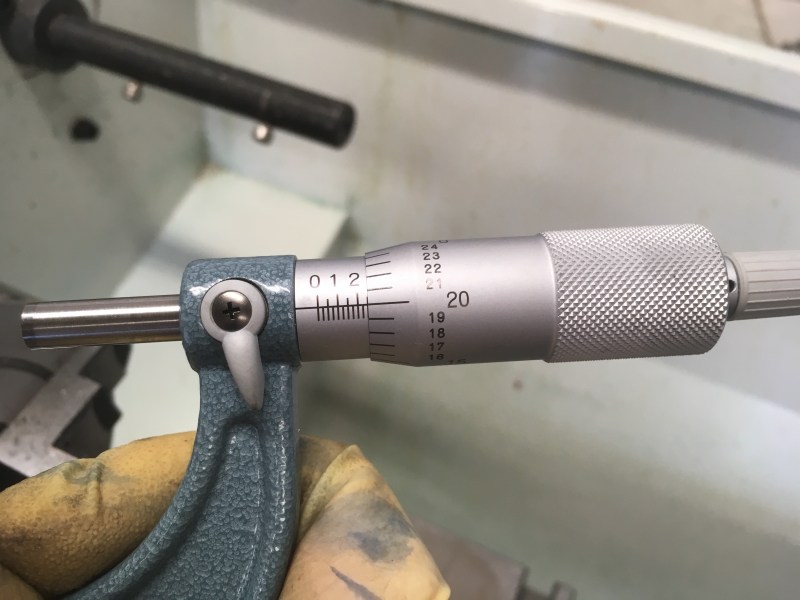
How close you want to get these measurements is up to you, but a tenth of a thousandth over 5-6″ is likely good enough for anything a hobbyist is going to need. Once you’re done, you can oil and store the test bar for use later on. With a relief cut of 30 thou or so, the same test bar can be reused several times.
That’s all there is to it! Cutting a test bar is an easy hour-long project that will teach you valuable lathe skills and build your confidence in the machine. Once you know you can trust the machine, you’ll know that any future problems exist only between the hand-wheels and the drawing*.
*That’s you.


” If they are different, the machine is cutting a taper, which means your bed has some twist”
Or the fixed headstock is not aligned correctly. If you are not sure of thatm, you cannot tell them appart.
So level the bed with a precision spirit, in fact it doesn’t need to be perfect level, but same level front and back.
Then you can cut the bar to test head alignment.
Same procedure for moving head, just turn the bar between centers as it ignore fixed head alignement.
This right here. More than anything else, in machine alignment you need to be very aware of any assumptions that you might be making and verify that they are indeed correct before proceeding.
Another source of potential taper is that the bolted-on headstock is simply not lined up with the bed.
You could have used the tailstock when making the barbell-shape.
But I am in no position to criticise, I haven’t even levelled my lathe yet. And it’s been years.
Using the tailstock to make the barbell assumes that the tailstock is correctly aligned. Perhaps use the tailstock to rough in the shape, but when making the actual test cuts, it should be held only by the chuck in the headstock.
It is far more reliable to do without assumptions. The steps I use are:
1) Eliminate bed twist by checking each end with a machine level, and adjusting one end, e.g. with the integral foot screws if fitted. Doing it with shims is more fiddly. Placing the machine level on top of the cross-slide works for me.
2) Turn the test bar between centres, then loosen the tailstock holding screws, and turn the lateral adjustment screw to reduce any error, showing as taper. Retighten the holding screws. Repeat till turning parallel with cross-slide locked.
3) After that minimal set-up, by all means try the now parallel turned test bar or a precision ground bar in your best chuck, with a dial gauge clamped on the cross-slide, but understand that you’re measuring chuck jaw runout as much as anything, and have no idea whether any of the taper is due to head misalignment.
4) Better is to hold the ground bar in a clean new collet in a clean collet chuck whose taper fits the spindle taper.
That’s probably good enough for even reasonably demanding hobby work.
And if Andy can get by without levelling his lathe, then I figure it’s not far off, as is. (Because I had to level mine before it would turn parallel – just centering the tailstock wasn’t enough.)
Well, my lathe is quite a sturdy thing. I doubt that they have been many lathes in the 10×20 class with quite so much metal in the bed and the base. The bed width is more than the centre height (which is common enough) but the bed depth is at least twice the centre height, which is far less common. https://photos.app.goo.gl/g5kvExAYDHpixrM86
I should perhaps have been more clear. I did mean that the shape could be roughed out with tailstock support. The test cuts for this test absolutely need to be taken with the bar unsupported.
There may be some value in checking the tailstock socket with a coaxial indicator. (And this is probably the quick way to dial an offsettable tailstock back in after turning a taper)
Not much reason to Like my dad said measure to a tenth of a thousandth of an inch, Mark it with life of chalk and cut it with an ax. He used a job bore for 30+ years.
Very nice article. A slightly better approach is to turn a Morse taper to fit the headstock, drill and tap the narrow end for a drawbar and then turn the collars. That will give you a bar you can use to test alignment with a dial indicator. A toolpost grinder is ideal, but a fine feed and light cut with a sharp tool are good enough. Getting a tenth is quite difficult as heating becomes a major problem.
I tried making an 18″ bar between centers. It was very educational. I still have the bar and will eventually take a crack at it again when I have a coolant flood setup. It’s pretty much impossible without coolant and probably still *very* difficult to hit a tenth on 6-8 collars over 18″.
Thanks to you Q-D, I’ll probably never own a metal lathe…
If I hadn’t read any of your lathe series, I probably would have bought a cheap (or crappy) one on a lark and never learned the essential fettlings that need to be carried out to make it truly useful, leaving it to gather dust in my shop.
B^)
Don’t be too pessimistic. Lathes are loads of fun and you don’t necessarily need to be set up for the very highest accuracy in order to do useful work. It depends what you’re trying to achieve – some kinds of job need more accuracy than others.
Also, accuracy is the sum total of your equipment setup and your own technique so as a beginner you don’t necessarily have to perfect everything right from the word go in one massive effort – you iterate in on a better and better level of adjustment over time as you learn, in a very enjoyable intermittent process.
At my age, and level of shop clutter, I wasn’t being pessimistic, as much as being realistic!
B^)
Rare indeed is an uncluttered shop in which any fun has been had. Fortunately you can do useful work with a small lathe if you don’t mind being unable to repair tractors or battleships. The oftrepeated advice to “buy the biggest you can afford” is true to a point but also misses the point that not everyone can spare the room or floor loading and lots of amazing stuff is done on small humble machines.
PS, mods, please give the “report” button an “are you sure” because sometimes I press it by accident when I mean “reply”. Very sorry.
Uh, buying a small lathe on a whim was the best thing i’ve done in recent history. It was the progenitor to the hobby and i’ve now been machining for a few years. Some of this stuff LOOKS/READS like its complex, but its really not. If you can follow process, a recipe or build a model, you can setup a lathe or a mill. The fun comes when you have different materials and learning what works best with what. HSS, Carbide – bright, pvd, tin, 304, 416, 4140. Oh my. Its truly an art to figure out what metals like and dont like and its once of the most fulfilling things once you FINALLY turn that perfect little cylinder.
I never thought i’d like machining, but once I got my first little Seig it was all over. I’ve since upgrade both lathe and mill and have a side CNC conversion project. Machining is truly one of the most fun things i’ve gotten into and its an utter satisfying and artistic hobby to boot. Give it a shot. You never know if you dont try.
Good summary.
One thing though: looks like you’ve got gloves on there. There seems to be a pretty strong consensus among machinists that wearing gloves while using a lathe is a serious safety risk. Apparently they can get caught in the chuck and drag your hand and arm into it. If I recall correctly, US OSHA guidance is very clear about “instruct operators not to wear gloves” for most machine tools.So is the UK HSE: “The wearing of gloves increases the risk of entanglement and is never acceptable near rotating parts of machinery such as manual metal working lathes”. I imagine most countries have something similar. While hackers are rightly skeptical about mindless healthandsafetyism, this one is serious. Swarf cuts are annoying, amputations are irreversible. Mind your fingers, ladies and gents.
That might be true for cloth and leather, but nitrile gloves are designed to rip apart.
I won’t bet a finger on this… A bunched nitrile glove is enough to pull your hand into the chuck, then flesh, tendon an bones will firmly pull your arm into it.
The practical machinist forums have more than a few stories of people wearing latex / nitrile gloves and having their injuries intensified because of it. The rubber grabs better than skin and takes longer to break than you think, sometimes taking skin with it. Apart from the obvious danger of drawing your hand into the machine.
Yet, even the sometimes paranoid professional safety organisations like US OSHA, UK HSE and the Dutch ARBO all advice against wearing ANY gloves when operating manual metal working machines like lathes and mills. Nitrile gloves are NOT designed to rip apart, they are designed to be sturdy enough to protect your hands during normal working conditions. But because they are softer and less tough than leather/skin they get caught easier. Even the slightest tug into a fast rotating chuck can be enough to do serious damage. DON’T RISK IT. If you really MUST protect your hands from cutting oil and such (Contact dermatitis from oils CAN happen, so I’m not saying it’s impossible or unnecessary) have a clean shop rag or gloves nearby to use ONLY with a completely stopped machine
There are a number of barrier creams and sprays that (in theory) keep irritating compounds from absorbing into your skin. Even a decent store brand skin moisturizer provides some protection or at least minimizes irritation.
Cream barrier work fine, unless working with water emulsion (and quite frankly, don’t do it on a small lathe).
“amputation” – That’s exactly how our safety guy at work worded it a few months ago. Our fabricator was taking a finishing pass on a shaft with a piece of sandpaper, glove got caught in the chuck and ripped his thumb off. After the initial shock wore off, those of us who understood just what the danger was had only one question – Why was he, of all people, wearing gloves? Only takes one moment of bad luck and the machine wins. . .
I did CNC maintenance for years my rule was never get your hands near moving parts, if you have to than you are not working safely:-[
If anyone like watching then reading:
This Old tony Lathe levelling https://www.youtube.com/watch?v=THkb-x35fwc
Lathes are dangerous, Wearing gloves is a really bad idea. About 15 years ago someone posted a photo to rec.crafts.metalworking of an accident at work. A guy with long hair leaned over the chuck, it caught his hair and a moment later he was very dead. It was not a pretty sight. The guy was bent over the lathe with blood everywhere.
Gloves /= long hair over chuck.
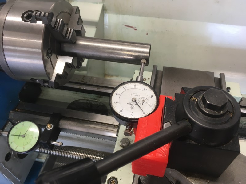
Trying to measure thou’s using a 3d printed plastic adapter seems like a bit of a silly idea to me tbh. As a metal working guy/engineer, I’d suspect the warpage in that adapter (from temperature and mechanical influences) is more than the deviation you’re trying to measure. You have a lathe, you could make one in metal/brass ;)
Really? Consider it’s only being used for a holder, and it’s position doesn’t matter much. The only thing that would matter in that case was deviation due to stress, and every indicator like that I’ve seen has very little required to move it, while any plastic piece of any size requires more force than that spring can provide. Even if it does move it, the spring’s force isn’t going to change much, if it’s at all close to aligned, so the deviation should be basically constant.
I’d love to see someone actually run the numbers, but I just can’t see them being off at that magnitude. Sure, it might be off but I’m suspecting many orders of magnitude less than anything readable on the dial. Also, I suspect, little to no difference compared to a brass holder. (If they are, I’d love to know I’m wrong.)
Why does every lathe discussion devolve in to a rant about wearing gloves? (or leaving the chuck key in the chuck).
People can make their own decisions about what they do in their own workshops in much the same way as they can choose to base jump or cave dive.
I don’t recall the previous articles in this series devolving “in to a rant about wearing gloves”
I think it’s useful to be made aware of how dangerous these tools are, especially for me as a hobbyist with no formal education or training. I pay even less attention when it’s a friend’s lathe but they’re just as dangerous
“Why does every lathe discussion devolve in to a rant about wearing gloves?”
Don’t know, it’s hard to put a finger on it… :)
Hi,
I wanted to know if there is any way to level the ways using the test bar method with an “offset headstock”. What I mean is that suppose your headstock is not parallel to the ways, now first you level the bed using the test bar method (by using the test bar method I actually mean not using any type of levels, etc. and just cutting something with the lathe) and then when you’re sure that your bed is leveled you can go on and align the headstock using the test bar method. So is it doable?
“Levelling” the bed is in fact removal of bed twist – to put the ways into one plane. The available adjustment is normally no more than levelling screws on the feet of the machine stand, and it is only one end which needs to be adjusted. (The bed does not need to be level, so long as both ends are parallel.)
OK, if you had e.g. a large diameter one metre long ground test bar with parallel precision grooves at 180 degrees separation, a precision sled to slide in those grooves, with an arm on each side, each holding a “tenths” DTI, then that could survey the bed twist from end to end, if you’re strong enough to lift it into place, it matches your bed length, and you could manufacture or buy it.
A precision machine level is not a pocket item, but manipulable with one hand, and infinitely more conveniently makes measurements to a higher resolution. It’s also a damn sight cheaper. Mine cost less than $200, and I just plonked it on top of the cross-slide, adjusted one lathe end to close to level, then wound the carriage from end to end. The “toolroom quality” lathe is only specified to +/- 0.001″ from end to end, and the machine level measure a darn sight better than that, permitting a precision machine installation.
While the article burbles obliquely about lathe twist, the next paragraph admits that the test bar is only used for headstock and tailstock alignment. In reality, though, what he’s measuring is his chuck runout. Get rid of that, and substitute a collet held directly in the spindle taper, if you want any indication of spindle to bed alignment. (Anyway, if the lathe is of good quality, then it is only the tailstock you’ll need to adjust.)
Well first of all I do have a precision level and I use it a lot too! And as you said it’s actually a very versatile instrument and you can actually get pretty creative with it for a lot of jobs. So I just want to think about this scenario and see if there is any solution to it the way I want or not.
The ground test bar that you suggested works but that’s essentially works like a precision level in this case and what I meant by “using a test bar” was cutting a test bar on our hypothetical lathe, with it’s headstock not parallel to the ways (both horizontally and vertically) and a twist in it’s bed, and measuring it directly for tapers. In this scenario you’ll get a compound taper from three different sources, right? Horizontal and vertical headstock misalignments and bed twist.
And what you said “measuring his chuck runout”, I think that’s not correct. Chuck runout doesn’t introduce any tapers in the turned piece and as long as you don’t remove the test bar from the chuck it’s perfectly accurate for determining bed twist/headstock misalignment. Put in other words you still get your headstock parallel to the ways with this method despite the fact that your chuck axis could as well be out of parallel after the alignment. (the chuck runout)
Regarding my hypothetical scenario, I think it’s doable myself. First for example you have to vary one the parameters (twist, horizontal/vertical misalignment) until you get your tapers to change direction, that’s the point where your chosen parameter is in it’s “center” (aligned) position. Then you go on to the next variable on so on…
Just finished a project to modify Weber Carburetor for external floats adjustment. I learned quickly that I had a messed up lathe when I cut 4mm by 2mm stainless tube. I tried to cut the OD to 0.135” and 1.4” long. Made a nice taper of 0.120” to 0.135” over that length. I thought of the test bar but opted for on the fly tailstock adjustments. The tube had enough thickness to let me tweak the tubes to the 0.135” give or take a couple thou but critical parallels. In my case I used the tube as my “tester”and 4 jaw chuck and tailstock center on the 2mm bore
Its a bit different with my lathe,it’s cutting unwanted taper in the inside diameter and it’s cutting straight on the outside diameter,what could cause this
If anyone sees this this late to the game… If I can’t lower the the right front foot any more, is raising the left rear the “same”? Would that have the same affect? Or which would I need to raise? Thanks!
Very good , clear and profesional explanation for this issue. Hope rest of good intentioned web blogers better go away. Most of them I believe are not machinist at all. Certainly is not that complicate task.