Examine Source Code To Assembly Mapping With PenguinTrace

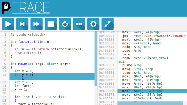
C-programmers who don’t have a mental model of what’s going on underneath their thin veneer of abstraction above assembly code are destined for trouble. In order to provide a convenient way to understand what C-code gets compiled to and how it runs on the machine, [Alex Beharrell] has created penguinTrace, a program which allows you to see what instructions your code compiles to, and examine how it executes.

While you can get somewhat similar functionality out of standard debuggers, penguinTrace was purpose-built to facilitate exploration of how the whole process works. You can single-step through the instructions your code compiled to, examine variables, and look at the stack — the usual debugger stuff — but structured more for exploration and learning than full-on debugging. Based on our experiences when we learned low-level programming, anything that can help novices build that all-important mental picture of what’s going on underneath is a good thing. But, since it was written with a secondary purpose of learning how debuggers themselves work, it’s a great opportunity for exploring that space, too.

The UI harnesses CodeMirror to provide a browser-based interface, and is configurable to use Clang or GCC for compilation. It supports AMD64/X86-64 and AArch64 architectures, and will run on Windows using WSL: if you’ve got a PC running Linux, a Raspberry Pi, or a Windows box, you’re good to go. The code is AGPL-licensed and available on GitHub. So, if you want to gain a better understanding of what happens when you compile and run “hello, world,” grab a copy and start exploring.

This isn’t the only way to debug, though – we previously featured an application that allows a type of debugging for the Arduino platform.


Make An Electroplating Marker, Because Plating Complex Objects Is Hard

If an object is conductive or has been given a conductive coating, it can be given a metal skin via electroplating. Electroplating is a simple process that is perfectly accessible to anyone in possession of vinegar, salt, a power supply, and some metal such as copper or nickel.

The process might be simple, but as with all such things there are a few gotchas. One of them is this: because electricity follows the path of least resistance, recessed areas of an object may not electroplate well (or at all) no matter how long the object is left immersed. To address this, [Brodie Fairhall] designed a 3D printed electroplating marker. The marker is essentially a more refined version of brush plating, and allows more precision and control than full immersion in an electrolyte bath.

[Brodie] created an excellent video that explains all one needs to start electroplating, and demonstrates using his marker to electroplate complex recessed shapes. Watch him coat a 3D-printed cat pendant in both copper and nickel in the video embedded below. It’s concise, well-edited, and chock full of useful tips.

Continue reading “Make An Electroplating Marker, Because Plating Complex Objects Is Hard”

Dark Absorbing Diodes Are No DAD Joke

We will confess that the authors of the Applied Physics Letters article “Experimental Demonstration of Energy Harvesting from the Sky using the Negative Illumination Effect of a Semiconductor Photodiode” never used the acronym DAD or the phrase “dark absorbing diode.” But we thought it was too good to pass up. The research work uses a type of diode to generate small amounts of power from darkness. Admittedly, the amount of power is small, but it is still an important result and could result in — another coined phrase — negative solar cells providing energy by taking advantage of the temperature differential between the cell and the night sky.

In theory — and with no atmosphere — the technique could only result in about 4 watts per square meter. Not only is this low compared to a solar panel’s 100 to 200 watts per square meter, but it is also far from the prototype’s 64 nanowatts per square meter. Clearly, this technology has a ways to go to become practical.

Continue reading “Dark Absorbing Diodes Are No DAD Joke”

Help Solve The Single-Transistor Latch Mystery

If you’ve spent any time on hackaday.io, you may have noticed that more than a few denizens of the site are fans of “alternative” electronic logic. Aiming to create digital circuits from such things as relays, vacuum tubes, discrete transistors, and occasionally diodes, they come up with designs that use these components in either antiquated or occasionally new and unexpected ways. This is exactly what [Mark Sherman] has done with his latest project, a single-transistor latch.

If you think every design has to compete with cutting-edge integrated circuits, or even must have an immediate practical application, you might as well stop reading now — and to play on the famous Louis Armstrong quip about jazz, if you have to ask why someone would do such a thing, you’ll never know.

Given that you’ve come this far, you’ll appreciate what [Mark] has come up with. It’s semi-well-known that the collector-emitter junction of a bipolar junction transistor (BJT) can exhibit a negative resistance characteristic when reverse-biased into avalanche breakdown. It’s this principle that allows a single BJT to be used as an ultra-simple LED flasher. [Mark] took this concept and ran with it, creating a single-transistor latch that can store one bit of information. As a bonus — or is it a requirement? — the transistor also drives an LED, so that you can visualize the state. We’ve seen a one-transistor flip-flop before, but that one also required diodes and an AC bias supply. In this new device, none of this is necessary, so it’s a step up according to the unwritten, unspoken, and generally agreed upon rules of the game.

In true hacker fashion, [Mark] came up with a working device without fully understanding exactly how it works.  We, too, are a little mystified at first glance. So, [Mark] is asking for your help in replicating and/or analyzing the circuit. He explains what he has found so far in the video after the break, but the main questions seem to revolve around why the base resistor is required, and why it works with 2N4401s but not 2N2222s.

So, Hackaday, what’s going on here? Sound off in the comments below.

Continue reading “Help Solve The Single-Transistor Latch Mystery”

An Easy Camera Slider Build

As smartphone cameras improve with each new generation, making quality video content is getting easier all the time. This means it takes a little more to stand out, so it pays to get creative with your cinematography. A slider is a great way to get some different shots, and you can build one pretty cheaply too (Youtube link, embedded below).

For smooth motion, [Nikodem Bartnik] used aluminium extrusion for the rails, along with some roller bearing wheels designed to suit. The wheels are built into a 3D printed carriage, which is also fitted with a spherical clamping camera mount. It’s all wrapped up with some socket head cap screws and 3D printed brackets to tie it all together.

Dimensional accuracy is key to the smooth operation of a slider, so you’ll want to have your printer set up well if you’re going to attempt this one. [Nikodem] demonstrates the slider is capable of taking the weight of an mid-range SLR with a tastefully sized lens, but if you’re going for something telephoto, you might want to go for something bigger. You could also consider a motorized rig instead. Video after the break.

Continue reading “An Easy Camera Slider Build”

Pushing 3D Printed Wheels And Transmissions To The Limit

What do you do if you want a robot with great mobility? Walking is hard, and wheels are good enough, especially if you use the ‘wheels within wheels’ Mecanum setup. But you need torque, too. That’s what makes this entry into the Hackaday Prize so fantastic. It’s a Mecanum wheel of sorts, with an integrated gear set that produces a phenomenal amount of torque using a small, cheap stepper motor.

The wheel itself if 3D printed and fully parametric, using nylon weed wacker filament for the treads. This allows the wheel to scoot back and forth like a Mecanum wheel, or at the very least like one of those hyper mobile wheeled robots you see from time to time. It goes backwards, forwards, and side to side, and also has a zero turn radius.

A 3D printed Mecanum wheel is great, but how on earth do you drive it? That problem is solved with this hybrid planetary/strain-wave  3D-printed gear set. [Daren] has created a very compact ‘single’ stage gear set that fits right on top of a stepper motor. It’s thin, flat, and has a gear reduction of about 66:1. That’s a lot of torque in a very small package. Both of these projects are combined, and together they represent a freaky wheel with a lot of torque.

Even though [Daren] doesn’t have a robot in mind for this build, these are most certainly the building blocks of a fantastic robot, and a great entry in the Hackaday Prize.

Continue reading “Pushing 3D Printed Wheels And Transmissions To The Limit”

Fun With Negative Resistance: Jellybean Transistors

The concept of negative resistance has always fascinated me. Of course, a true negative resistance is not possible, and what is meant is a negative differential resistance (NDR). But of course knowing the correct term doesn’t do anything to demystify the topic. Negative resistance sounds like an unusual effect, but it turns out to be relatively common, showing up in places like neon lamps and a number of semiconductor structures. Now’s as good a time as any to dig in and learn more about this common principle.

NDR means a portion of a device’s I/V curve where the current falls with increasing applied voltage. The best-known semiconductor device exhibiting negative resistance is the tunnel diode, also known as the Esaki diode after one of the Nobel-Prize-winning discoverers of the quantum tunneling effect responsible for its operation. These diodes can perform at tremendous speeds; the fastest oscilloscope designs relied on them for many years. As the transistor and other technologies improved, however, these diodes were sidelined for many applications, and new-production models aren’t widely available — a sad state for would-be NDR hackers. But, all hope is not lost.

Rummaging through some old notebooks, I rediscovered an NDR design I came up with in 2002 using two common NPN transistors and a handful of resistors; many readers will already have the components necessary to experiment with similar circuits. In this article, we’ll have a look at what you can do with junkbox-class parts, and in a future article we’ll explore the topic with some real tunnel diodes.

So, let’s see what you can do with a couple of jellybean transistors!

Continue reading “Fun With Negative Resistance: Jellybean Transistors”