Reverse Engineering Silicon, One Transistor At A Time

Many of will have marveled at the feats of reverse engineering achieved by decapping integrated circuits and decoding their secrets by examining the raw silicon die. Few of us will have a go for ourselves, but that doesn’t stop the process being a fascinating one. Fortunately [Ryan Cornateanu] is on hand with a step-by-step description of his journey into the art of decapping, as he takes on what might seem an unlikely subject in the form of the CH340 USB to serial chip you’ll find on an Arduino Nano board.

Starting with hot sulphuric acid is probably not everyone’s idea of a day at the bench, but having used it to strip the epoxy from the CH340, he’s able to take a look under the microscope. This is no ordinary microscope but a metallurgists instrument designed to light the top of the sample from one side with polarised light. This allows him to identify an area of mask ROM and zoom in on the transistors that make each individual bit.

At this point the chemistry moves into the downright scary as he reaches for the hydrofluoric acid and has to use a PTFE container because HF is notorious for its voracious reactivity. This allows him to take away the interconnects and look at the transistor layer. He can then with a bit of computer vision processing help extract a bit layer map, which with some experimentation and guesswork can be manipulated into a firmware dump. Even then it’s not done, because he takes us into the world of disassembly of what is an unknown architecture. Definitely worth a read for the armchair chip enthusiast.

If you’re thirsty for more, of course we have to direct you towards the work of [Ken Shirriff].

This Vintage LED Matrix Lives In A Gold Bathtub

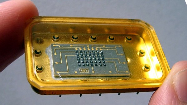
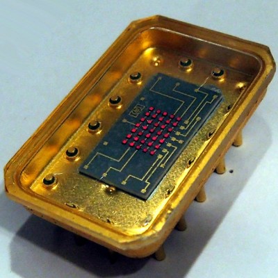
Early LED displays came in all sorts of configurations. Because the LED was fairly new technology, all kinds of ideas were getting tried, and with all that work there was plenty of opportunity for hardware that didn’t make the cut to fall into obscurity. That’s exactly what happened to the Hewlett-Packard 5082-7002, a 5×7 LED matrix display with something many of its brethren didn’t: an oversized gold tub to sit in.

It doesn’t seem that these displays were ever used in any actual products, and its origins are a mystery, but the device itself was nevertheless assigned an HP part number. Beyond that, not much is known about them, but [Industrial Alchemy] reminds us that many early LED devices were poorly documented and never produced in any real quantities. They became forgotten hardware, waiting to be rediscovered.

The 5082-7002 has a oversized gold tub that makes the 5×7 LED matrix mounted inside look puny by comparison, and reading any display made from these units would be difficult because the large size of the device would mean a lot of empty space between each character or digit. But it’s definitely got a striking look to it, no doubt about that.

What’s neat is that the 5802-7002 actually showed up in a video we featured with a look back at cool old LED technology. If you would like to (briefly) see the HP 5802-7002 a bit closer under a microscope, here is a link to the video, cued to 2:19.

When The Right Tool Is Wrong

I’m a firm believer in using the right tool for the job. And one of the most fantastic things about open-source software tools is that nothing stops you from trying them all. For instance, I’ve been going back and forth between a couple, maybe three, CAD/CAM tools over the past few weeks. They each have their strengths and weaknesses, and so if I’m doing a simpler job, I use the simpler software, because it’s quicker and, well, simpler. But I’ve got to cut it out, at least for a while, and I’ll tell you why.

The first of the packages is FreeCAD, and it’s an extremely capable piece of CAD/CAM software. It can do everything, or so it seems. But it’s got a long shallow learning curve, and I’m only about halfway up. I’m at the stage where I should be hammering out simple “hello world” parts for practice. I say, I should be.

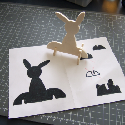
Fortunately/unfortunately, some Hackaday readers introduced me to KrabzCAM through the comments. It’s significantly less feature-full than FreeCAD, but it gets the job of turning your wife’s sketches of bunnies into Easter decorations done in a jiffy. For simple stuff like that, it’s a nice simple tool, and is the perfect fit for 2D CAM jobs. It’s got some other nice features, and it handles laser engraving nicely as well. And that’s the problem.

Doing the simple stuff with KrabzCAM means that when I do finally turn back to FreeCAD, I’m working on a more challenging project — using techniques that I’m not necessarily up to speed on. So I’ll put the time in, but find myself still stumbling over the introductory “hello world” stuff like navigation and project setup.

I know — #first-world-hacker-problems. “Poor Elliot has access to too many useful tools, with strengths that make them fit different jobs!” And honestly, I’m stoked to have so many good options — that wasn’t the case five years ago. But in this case, using the right tool for the job is wrong for me learning the other tool.

On reflection, this is related to the never-try-anything-new-because-your-current-tools-work-just-fine problem. And the solution to that one is to simply bite the bullet and stick it out with FreeCAD until I get proficient. But KrabzCAM works so well for those small 2D jobs…

A hacker’s life is hard.

You Can Now Build Your Own Glowing LED D20 (with A Whopping 2,400 LEDs)

The D20, or twenty-sided die, is most commonly known in the shape of a regular icosahedron. It’s a fantastic, enchanting geometry, and one that has held the balance of fate in innumerable tabletop roleplaying games over the years. It was this sacred geometry that [Greg Davill] chose to bless with the glory of glowing RGB LEDs. Now, [Greg] has shared the files so you can build your own.

The development blog of the D20 is a great read, highlighting the challenges of creating such a compact item that glows so brilliantly. The design uses a full 2400 1.5 mm x 1.5mm LEDs, in the old-school RGB style, split evenly between the twenty sides. That’s right, there’s no fancy self-addressing smart LEDs here — each LED is manually controlled directly by [Greg]’s hardware. A SAMD51 and ICE40UP5K FPGA are put to work running the displays. Each panel is held together in a barely-there 3D printed frame, linked together with ribbon cables to keep things compact. A Sony camera battery is slotted inside the tight confines of the frame to supply the necessary power.

We first covered the project late last year, and it’s great to see it out there now in a form that’s readily reproduced. Assembly of such a board is not for the faint of heart, however, with plenty of fine SMD parts to tangle with. We suspect this is just yet another salvo in the ongoing arms race of LED glowables, and we can’t wait to see what [Greg] — and the rest of the community — comes out with next. If you’ve got a lead on the new glowing hotness, let us know. Video after the break.

Continue reading “You Can Now Build Your Own Glowing LED D20 (with A Whopping 2,400 LEDs)”

Playing Snake On A PCB!

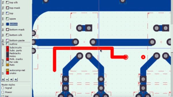
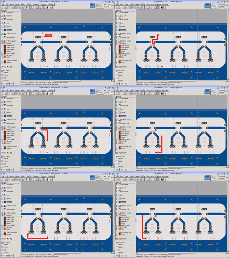
When conversation turns to the older Nokia mobile phones, it’s unlikely to be the long battery life or ability to conjure a signal out of thin air that tickles people’s memory, instead it’s the Snake game built into the stock firmware. Snake was an addictive yet extremely simple game in which a line of pixels — the snake in question — was navigated around the screen to eat the fruit without crashing into walls or itself. As the game progressed the snake grew in length, making it a surprisingly difficult challenge. If you hanker for Snake, as [VK5HSE ] writes, you can now play it in a PCB layout.

The software in question is PCB-RND, a cross-platform open-source PCB CAD tool, and the game is achieved through the magic of user scripting. Simply download the script, run it in your favourite circuit board, and away you go!

We can’t imagine a productive use for this piece of software, but it wouldn’t surprise us to see a snake slithering into a few boards we feature. It does provide a handy reminder though of the power in your PCB CAD tool’s scripting features, something it’s likely not many of us use to their full potential.

We’ve featured [VK5HSE]’s work with PCB-RND before, in a very useful Eagle import tool.

Finger Bend Is A Textile Flex Sensor You Can Sew At Home

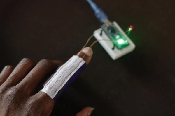
So often, we use control devices for electronics that involve our fingers directly grasping, touching, or moving another object or surface. It’s less common for us to use interfaces that detect the motion of our bodies directly. Flex sensors are one way to do that, and it’s exactly what [WillpowerStudios] aims to do with Finger Bend.

The construction of the sensor is simple, using piezoresistive fabric which changes its resistance when deformed. By sewing this into a sheath that can be placed on the finger, and wiring it up with conductive threads, it can be used to detect the flexion of the wearer’s digits by sampling the resistance with an analog to digital converter on any garden variety microcontroller. Expanding the technique to a full hand is as simple as creating a Finger Bend per digit and wiring up each one to its own ADC channel. If you want to get really fancy, you could even scan through them at speed with a multiplexer.

It’s similar to the technology used in Nintendo’s infamous Power Glove, and while it’s never caught on in the mainstream, it may have applications yet. Video after the break

Continue reading “Finger Bend Is A Textile Flex Sensor You Can Sew At Home”

FreeCAD Takes Off With A Rocket Design Workbench

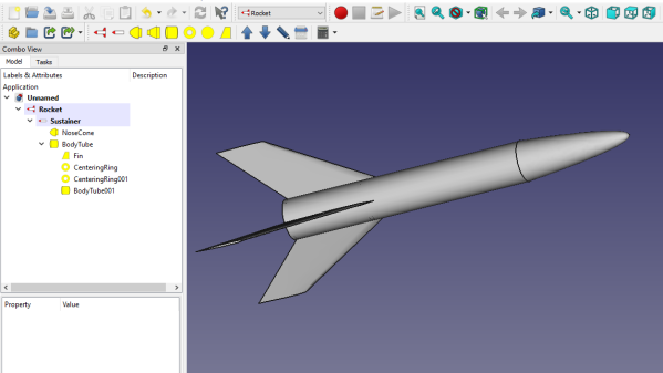
Here’s how FreeCAD works: the program’s design space is separated into different “workbenches”, each of which is intended for a particular set of operations, and a piece of work can be moved between them as needed. There is a sketching workbench, a part design workbench, and now a Rocket workbench has been added to the healthy ecosystem of FreeCAD add-ons. There’s even a series of video tutorials; ain’t open source grand?

It all started when [concretedog] posted on the FreeCAD forums, making a strong case for a Rocket-themed workbench. People got interested, and a short while later [DavesRocketShop] had some useful tools up and running. Here’s a blog post by [concretedog] which goes into detail and background, and while the Rocket workbench is available via FreeCAD’s add-on manager, the very latest experimental builds are available for manual installation on [Dave]’s GitHub repository.

This sort of development and utility is exactly the kind of thing our own Elliot Williams was describing when he made the point that one of open source’s greatest strengths is in the little things, like the FreeCAD ecosystem letting people scratch strange and specific itches, and the ability to share those solutions with others.